Episode 9: Scores!
Implementing the score display and do some polishing is what we're doing in this episode. Bit things aren't that simple, because we really want to rescue one of those tiny scan lines and therefor become involved in cycle counts once more and are racing the beam for real. Revards are a polished game display and some further insights.
Displaying Scores
It's time to get rid of those dummy stripes and have some scores displayed on top of the playfield. This comes with a few requirements: We need some additional pointers (4 times 16-bit) to store the base address of the numerals to be rendered by the player sprites and also a few other of oure scarce RAM locations. In order to not do divisions by 10 each frame, we'll store the two didgits of a score (00...99) in two bytes, but run them around at 10 instead of 256. Further, we need a location to store the current color for each of the two ships, since we'll have to change the sprite color midways each frame after we rendered the score display and the ships are displayed at varying colors to represent states. There go another 12 RAM locations…
There will be 4 score numerals in total and they will come in pairs of two and between these pairs, there'll be considerable space. We may implement this by lining up the two player sprites and set them up to be replicated at a distance. The widest distance available on the TIA is 64 pixels and this is just about fine. Moreover, 64 pixels is 21 CPU cycles and we'll have plenty of time to load and rewrite the player sprites midways, without having to refer to the 48 pixel sprite trick. (I'm afraid, we'll going to become involve in this one while doing the title screen, probably next episode.)
Scores, sprite layout and measurements.
The TIA registers for replicating sprites ar NUSIZ0 and NUSIZ1 for Player0 and Player1, respectively.:
TIA – NUSIZ0, NUSIZ1
| D2 | D1 | D0 | 1/2 TV line (80 clocks) 8 clocks/pixels per block | Description | ||||||||
|---|---|---|---|---|---|---|---|---|---|---|---|---|
| 0 | 0 | 0 | X | . | . | . | . | . | . | . | . | one copy |
| 0 | 0 | 1 | X | . | X | . | . | . | . | . | . | 2 copies – close |
| 0 | 1 | 0 | X | . | . | . | X | . | . | . | . | 2 copies – medium |
| 0 | 1 | 1 | X | . | X | . | X | . | . | . | . | 3 copies – close |
| 1 | 0 | 0 | X | . | . | . | . | . | . | . | X | 2 copies – wide |
| 1 | 0 | 1 | X | X | . | . | . | . | . | . | . | double size player |
| 1 | 1 | 0 | X | . | . | . | X | . | . | . | X | 3 copies – medium |
| 1 | 1 | 1 | X | X | X | X | . | . | . | . | . | quad sized player |
The combination we're lookin for is value 4 (2 copies, wide) and, counting the blocks in the table, a sprite will reoccur for the second copy 8 blocks or 64 pixels after the left edge of the first one. Next is setting up the base addresses for the numerals. A digit is 8px high (including a terminating 0) and they are stored in reverse order in memory like this:
Digits
    .byte %00000000 ; |        |
    .byte %01111111 ; | XXXXXXX|
    .byte %01000011 ; | X    XX|
    .byte %01000011 ; | X    XX|
    .byte %01000011 ; | X    XX|
    .byte %01000001 ; | X     X|
    .byte %01000001 ; | X     X|
    .byte %01111111 ; | XXXXXXX|
    .byte %00000000 ; |        |
    .byte %00011100 ; |   XXX  |
    .byte %00011100 ; |   XXX  |
    .byte %00011100 ; |   XXX  |
    .byte %00001000 ; |    X   |
    .byte %00001000 ; |    X   |
    .byte %00001000 ; |    X   |
    .byte %00011000 ; |   XX   |
    .byte %00000000 ; |        |
    .byte %01111111 ; | XXXXXXX|
    .byte %01000000 ; | X      |
    .byte %01000000 ; | X      |
    .byte %01111111 ; | XXXXXXX|
    .byte %00000011 ; |      XX|
    .byte %00000011 ; |      XX|
    .byte %01111111 ; | XXXXXXX|
    .byte %00000000 ; |        |
    .byte %01111111 ; | XXXXXXX|
    .byte %00000011 ; |      XX|
    .byte %00000011 ; |      XX|
    .byte %00011111 ; |   XXXXX|
    .byte %00000010 ; |      X |
    .byte %00000010 ; |      X |
    .byte %01111110 ; | XXXXXX |
    (...)
You get the idea. Due to this arrangement, well have to set up base addresses at offsets of 8, while the scores come at single step intervals. A case for multiplying by shifts. This is accomplished by a tiny subroutine, setting up base addresses (sd0...sd3, 16-bit, LO-bytes start 2 bytes apart) to be used as pointers for the individual score digits:
SetScore                   ; score in A, digit pos in X (offset 2: 0, 2, 4, 6)
    ldy #>Digits
    sty sd0 + 1,X
    asl
    asl
    asl
    clc
    adc #<Digits
    sta sd0,X
    bcc setScoreDone
    inc sd0 + 1,X
setScoreDone
    rts
We call this during sprite setup in VBLANK:
SetScores
    lda score0 + 1
    ldx #0
    jsr SetScore
    lda score0
    ldx #2
    jsr SetScore
    lda score1 + 1
    ldx #4
    jsr SetScore
    lda score1
    ldx #6
    jsr SetScore

HPositioning            ; horizontal sprite positioning
    sta WSYNC
    lda #40             ; player0 (score display, digit 1)
    ldx #0
    jsr bzoneRepos
    lda #50             ; player1 (score display, digit 1)
    ldx #1
And finally render the scores in a loop on top of the playfield:
;;;;;;;;;;;;;;;;;;;;;;;;;;;;;;;;;;;;;;;;;;;;;;;;;;;;;;;;;;;;;;;;;;;;;;;
;
; Visible Kernel
;
;;;;;;;;;;;;;;;;;;;;;;;;;;;;;;;;;;;;;;;;;;;;;;;;;;;;;;;;;;;;;;;;;;;;;;;

Scores
    lda #0
    sta COLUBK          ; set background color
    sta COLUPF          ; set playfield color
    sta REFP1           ; player 1 normal orientation
    lda #ScoreClr       ; set sprite color
    sta COLUP0
    sta COLUP1
    lda #4              ; sprites to two copies, wide spread
    sta NUSIZ0
    sta NUSIZ1
    ldy #7

ScoresLoop
    sta WSYNC
    lda (sd0),Y
    sta GRP0
    lda (sd1),Y
    sta GRP1
    nop
    (...)               ; insert smart guess for midfields timing
    nop
    lda (sd2),Y
    sta GRP0
    lda (sd3),Y
    sta GRP1
    dey
    bpl ScoresLoop
Since the last byte rendered is a zero byte for each of the digits, the sprites are off after the loop. What's left to do, is setting up the player sprites in order to display the ships and reposition them. Here we must not forget to reset any of the various other HMxx registers to zero (by strobing HMCLR), or the respective objects will moved again, when we strobe HMOVE for the fine adjustment. After a few lines of black (mind the black pixels on the left caused by HMOVE), we're ready for the border.
In the actual code, we also add a striped effect at the left and right border and also switch the sprite colors between alternating scan lines order to modulate them slightly. (Otherwise, they do feel a bit bright, also, this matches the overall design.) And, lo and behold, there are our scores:
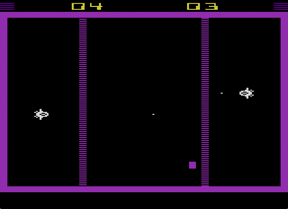
Behold the neat scores. (Screenshot of emulation in Stella.)
Click the image for a live preview in online emulation.
Racing the Beam
Or The Quest for a Scan Line
If you are having a closer look at the image, you may discern that there are just two black scanlines between the scores and the top-border of the playfiel, while we might expect at least 3, or rather 4 of them, when using the Battlezone repositioning routine. Considering the constant positions of the ship sprites, each well apart from the other, we may do better than this. We may even do it in a single line, but two are just about right for our game.
Instead of calling the subroutine, which will start on each call with a strobe of WSYNC and thus wait for the next scan line, we may do it by hand. The ships are positioned at coordinates 20 and 124, adding 68 TIA color clocks of HBLANK to this, at 88 and 202. We should be able to hit the appropriate cycles by hand and also figure out the right adjustment factor for the horizontal movement registers. And this is what we're looking for in particular:
Horizontal Motion Registers (HMP0, HMP1, HMM0, HMM1, HMBL)
| D7 | D6 | D5 | D4 | Clocks | Effect |
|---|---|---|---|---|---|
| 0 | 1 | 1 | 1 | +7 | Move left indicated number of clocks |
| 0 | 1 | 1 | 0 | +6 | |
| 0 | 1 | 0 | 1 | +5 | |
| 0 | 1 | 0 | 0 | +4 | |
| 0 | 0 | 1 | 1 | +3 | |
| 0 | 0 | 1 | 0 | +2 | |
| 0 | 0 | 0 | 1 | +1 | |
| 0 | 0 | 0 | 0 | 0 | No Motion |
| 1 | 1 | 1 | 1 | -1 | Move right indicated number of clocks |
| 1 | 1 | 1 | 0 | -2 | |
| 1 | 1 | 0 | 1 | -3 | |
| 1 | 1 | 0 | 0 | -4 | |
| 1 | 0 | 1 | 1 | -5 | |
| 1 | 0 | 1 | 0 | -6 | |
| 1 | 0 | 0 | 1 | -7 | |
| 1 | 0 | 0 | 0 | -8 |
Setting one of the motion registers, gives it a head start over the main scan line counter (see column “Clocks”), which is also causing the 8px of playfield/background blackout, when HMOVE is strobed.
(Strobing register HMCLR reset all horizontal motion registers to zero.)
In fact, the procedure involves a bit of trial and error. There are several factors to be considered. E.g., it's not about when we issue the strobe operation, but when it is actually performed and the address lines and write-enable of the TIA are touched. Obviously, this is only happening near the end of the instruction cyles of the store instruction used for this. Any cycles, which are used for address lookup are to be considered. Therefor, we're not counting up until just before the write instruction, but towards its end. Including this in our consideration, we arrive by the right adjustment value by rounding up the result by a division by 3 (there are 3 TIA color clocks per CPU cycle) and determining any negative remainder (offset to the left). However, this is not the end of the story: Experiments reveal that there is apparently a delay of 2 CPU cycles (6 color clocks) until the strobe takes effect. By this, we arrive at the following values:
Ship0, X = 20
       =>  68 HBLANK + 20 = 88 = 30 × 3 - 2 adjustement
       =>  effective at 28 (end of strobe) + 2 cycles
       =>  start of "sta RESP0" (3 cycles) at cycle 25

Ship1, X = 134
       =>  68 HBLANK + 134 = 202 = 68 × 3 - 2 adjustement
       =>  effective at 66 (end of strobe) + 2 cycles
       =>  start of "sta RESP1" (3 cycles) at cycle 63
As we may see, all it takes is to count up to cycles 25 and 63 and hit REPS0 and RESP1 respectively. We also have to load the adjustment factors for 2 color cycles to the left ($20) into HMP0 and HMP1, respectively, and strobe HMOVE at the very beginning of the next scan line. Having a look at our layout, we could have interwoven this with the last display line of our scores. However, it's not worth the effort, since two lines of black is all we're heading for, for aestetical reasons. But we may still fill the cycles, we have to wait, with something useful. In our case, we're fitting all the cleanup and setup stuff in this line, carefully considering the cycle count. As it happens, there's nothing left to do after the HMOVE starting the second black line…
(Note: we're doing just the first 7 iterations of the score loop and are then switching off the sprites near the beginning of the new scan line. The sprites in memory remain the same, 8 bytes long/high, to maintain the 8-bytes offset between them. Therefore, the score loop is now iterating from 7 down to 1 and falls through at 0 to the next line.)
     (...)
     bne ScoresLoop

RepositionPlayers          ; there's apparently a delay of 2 CPU cycles after strobing RESPx
    sta WSYNC              ;         wait for HSYNC...
    lda #%00100000         ;  0: (2) ship0 at 68 +  20 = 30 x 3 - 2; start strobe at 25
    sta HMP0               ;  2: (3) set HMP0 to 2 pixels left
    lda #%00100000         ;  5: (2) ship1 at 68 + 134 = 68 x 3 - 2; start strobe at 63
    sta HMP1               ;  7: (3) set HMP1 to 2 pixels left
    lda #0                 ; 10: (2)
    sta PF0                ; 12: (3) playfield off
    sta GRP0               ; 15: (3) player0 off
    sta GRP1               ; 18: (3) player1 off; now at 21, 4 cycles to burn
    nop                    ; 21: (2)
    nop                    ; 23: (2)
    sta RESP0              ; 25: (3) strobe player0, now at 28 (+2 = 30)
    sta HMM0               ; 28: (3) reset HMxx registers for missiles and ball
    sta HMM1               ; 31: (3)
    sta HMBL               ; 34: (3)
    sta NUSIZ0             ; 37: (3) set players to single copy, normal size
    sta NUSIZ1             ; 40: (3)
    lda ship0Clr           ; 43: (3) set player0 color
    sta COLUP0             ; 46: (3)
    lda ship1Clr           ; 49: (3) set player1 color
    sta COLUP1             ; 52: (3)
    lda #8                 ; 55: (2) flip player 1 horizontally
    sta REFP1              ; 57: (3) now at 60, 3 cycles to burn
    lda $80                ; 60: (3)
    sta RESP1              ; 63: (3) strobe player1, now at 66 (+2 = 68)
    sta WSYNC              ; 66:     repositioning done
    sta HMOVE              ; strobe HMOVE for fine adjustment

TopBorder
    sta WSYNC
    (...)
Note: Mind that the HMxx registers are easier reset by just strobing HMCLR, but we have cycles to burn…
Polishing the Game Mechanics (and Wasting RAM, Too)
As it was, the ships move vertically by 1.5 pixels per frame. This is an about right compromise, regarding accuracy and speed, but it it feels a bit clumsy. Therefor, we add an adaptive acceleration, starting at half a pixel and smoothly accelerating up to 2 pixels. This allows both for accuracy and for quick reactions and provides the smooth controls, our game deserves. Still, we have to store the state of the accelaration somewhere and so we have to dedicate another two bytes of RAM, one for each of the ships.
By this, we're nearly running out of RAM, at least, we can already feel the nightmarish presence of RAM-top: The various variables are occupying a space from $80 to $B9 and the scan-line routine occupies space from $C0 to $E8, leaving inbetween just the handfull of bytes, we'll need to keep track of the sound effects, we're going to add. We have still a bit of space left at the top, since we're never going deeper than two levels of subroutine calls. Therfore, as it is, 4 bytes of stack is all we need. However, if we consider the Atari 7800 as a target platform as well, there are interrupts and each interrupt will require another hefty 6 bytes of stack. (So to be on the safe side, we'll actually want at least stack space from $FF down to $F0.) — Good, we're actually finished with the basic game!
Have a look at it here!
▶ Next: Episode 10: Title Graphics
◀ Previous: Episode 8: Completing the Game Mechanics
▲ Back to the index.
April 2018, Vienna, Austria
www.masswerk.at – contact me.
— This series is part of Retrochallenge 2018/04. —