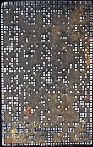
Code plate of the IBM 026.
Image: Bob Blaylock, CC BY-SA 3.0, Wikimedia Commons.
Card punches of various types, models and makes featured an option to print the characters encoded by the holes punched in any of the columns in human readable form onto the top of the card. While it is well known that these characters were printed by a 5 × 7 dot matrix, comprehensive information on what these character glyphs looked like exactly and how they were effected is rather rare. What may be more reasonable than reconstructing them from their very form of technical encoding?
Recently, while soaring through various information on character encodings and, eventually, card punches, I stumbled upon a rather interesting, astoundingly flexible, and quite arcane piece of technology: The IBM card punch code plate.
The code plate is a tiny, roughly stamp-sized piece of metal (for the IBM 029/129 the “IBM Field Engineering Theory of Operation” (S225-3358-4) [1] gives dimensions of
And this is, what it looks like, here for the IBM 026:
Code plate of the IBM 026.
Image: Bob Blaylock, CC BY-SA 3.0, Wikimedia Commons.
And the complete assembly for the IBM 029 in the IBM Field Engineering Theory of Operation manual:
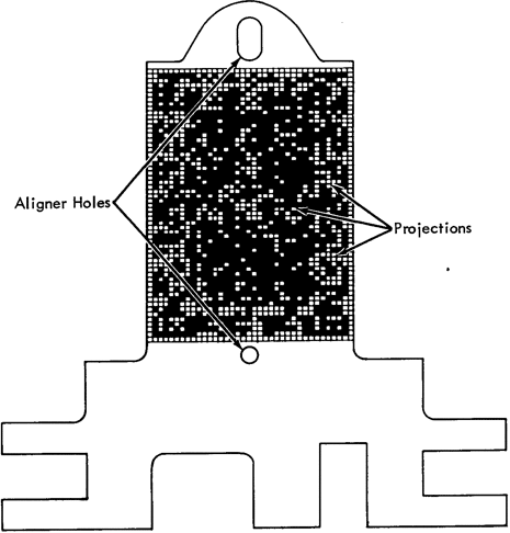
Engineering drawing of the code plate of the IBM 029. IBM S225-3358-4 [1].
Now, the arragement of the projections (often just called pins) doesn't give away easily to any comprehensible encoding pattern. The arcane nature of the encoding scheme might be kind of a setback, since it also provides an astounding amount of flexibility. Compare this passage on the IBM 029 in “Computer Resurrection — The Bulletin of the Computer Conservation Society”, No. 54, Spring 2011:
Equally ingenious was the printing mechanism. As each column was punched, the character was printed, dot matrix-style. A 5×7 matrix was employed with up to 35 wires being pressed down onto an ink ribbon (and thence to the card) simultaneously. At the other end of the wires was a postage stamp sized “code plate” with 35×64 (or 35×48) minute pillars protruding from it. Think of an array of tiny, tiny Lego bricks. By milling off most of the pillars, a mechanical, read-only binary store could be manufactured.
As a character was punched, the plate moved to one of 64 positions and then pushed down. Where the pillar was still in situ, the wire would be forced down and a dot printed. Or not, as the case may be. Of course, this mechanism required considerable precision in manufacture and setting up, but then any card punch does, so it was well within IBM’s capability.
We started by observing that the 029 could be found almost anywhere. IBM installations had them, but so did many others. One of the headaches of those days was that each manufacturer used a different card code. Often a manufacturer used different codes for different ranges of computer. Yet the 029 supported them all. How? Here, I fear, we must enter the realms of speculation. But it is at least informed speculation.
Try as I may, I can find no provision for varying the mapping from keys to hole arrangement. But, since the hole combinations were the same from one code to another - only the meanings varied - swapping the keytops cured half the problem. Which leaves the printing mechanism to be dealt with. But the printing was controlled by the code plate, so fitting a different code plate with a different binary pattern recorded upon it, changes the meaning of each key. You have to admit that’s clever.
(Dik Leatherdale, The Ubiquitous IBM 029 Card Punch)
So — how does the character encoding mechanism work?
First, the codeplate isn't doing the printing by itself, it generates the encoding by establishing connections to a set of 35 printing wires that are actually effecting the printing. This is, what the arrangement looks like, again from the IBM 029 Field Engineering Theory of Operation:
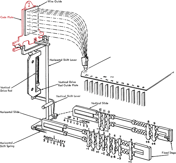
Schematic drawing of the printing mechanism of the IBM 026/029/129.
IBM S225-3358-4 [1]. (Color by me; N.L.)
Note: Mind the 7 × 8 encoding grid (given by the shaft values -3 … +3 and -3 … +4), which rather represents the mechanism of the model 026 than that of models 029/129, which used an 8 × 8 encoding scheme. — Apparently, they were the same, even in the eyes of IBM engineers.
And this is where the code plate fits into the actual mechanical assembly:
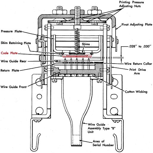
Engineering drawing of the printing assembly of the IBM 026.
IBM S225-635-5 [2]. (Color by me; N.L.)
The printing mechanism is pretty much the same for any of the classic IBM card punches: While punching, the code plate is moved by a set of shafts and cams, the print interposers, into correct position to produce the dot matrix pattern for the respective character. This movement happens for every code punched, regardless of wheather printing is on or off.
The pins are arranged on the code plate in a rectangular code grid repeated for 35 cells so that the pins in each of the cells may transfer mechanical pressure to one of the 35 (5 × 7) printing wires. The pattern of the character matrix is effected by the plate being moved by the actuators to the respective offsets of the encoding grid and by the presence (or absence) of a pin in that particular location.
In deed, a mechanical, programable, binary read only memory, made of a tiny piece of bare metal.
Here are the mechanisms, encoding schemes, and the generated character matrix for the IBM 026, 029, and 129 card punches, presented as interactive infographics:
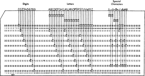
The code plate of the IBM 026 features 47 valid (i.e., printing) character codes arranged in a
To select a given character, the code plate is moved for every punch relatively to the fixed printing wires, regardless, wheather printing is on or off. (Reportedly, the mechanism was designed for character codes and rapid movements effected by some combinations of binary representions could cause mechanical failure.) Here, we rather show the plate in fixed position and move the printing wires instead:
Red squares represent active pins, orange outlines active positions without a pin, black squares inactive pins, and a lightgray circle marks the neutral position of a given cell of the character matrix (code grid 0/0).
The IBM 029 and IBM 129 share the same code plate featuring 63 valid character codes arranged in an 8 × 8 code grid. Like we've already seen it with the model 026, the coordinates (-3 … +4 / -3 … +4) of the code grid are repeated over the cells of the plate in the positions of the 5 × 7 character matrix, rows arranged upside down. Again, the pins belonging to a character are identified by their relative position inside a given cell.
Red squares represent active pins, orange outlines active positions without a pin, black squares inactive pins, and a lightgray circle marks the neutral position of a given cell of the character matrix (code grid 0/0).
Finally, here are the encoding grids as presented in the IBM manuals. These tables also show the arrangement of the characters in relation to their respective punch codes. (Mind that the rows are laid out upside-down as compared to the physical arrangement found on the code plate.)
IBM 026:
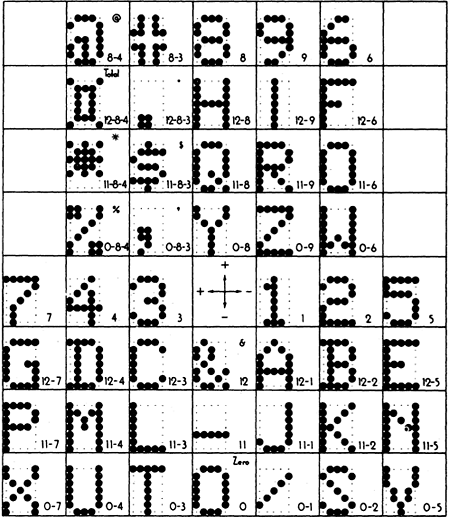
Character encoding of the IBM 026 card punch.
IBM Field Engineering Maintenance Manual, 24-Base Machines; S225-635-5 [2].
IBM 029, 129:
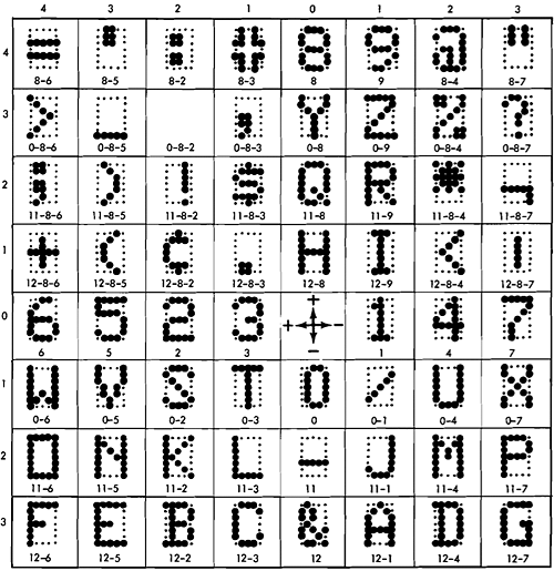
Character encoding of the IBM 029 and 129 card punch.
IBM Field Engineering Maintenance Manual, 29 Card Punch; S225-3357-3 [3] (also in [4]).
While most of the character set of the model 026 made it to the 029/129 — with the notable exception of the square lozenge (⌑)* —, some punctations and mathematical signs vital for programming and the cent currency sign where added. Moreover, the letter “O” and the number zero, which, while being produced by destinctive encodings, shared the same form on the 026, were altered for visual distinction. Also, the letter “I” received slab-serifs (to separate it visually from the newly added vertical bar) and the glyph representing the number 4 was changed a little by adding another dot for a closed form.
Overall, the changes we see in the font of the IBM 029/129 are representative for the new role of punched cards shifting the focus from traditional book keeping and fixed data fields to the requirements of programming and electronic data procssing.
(Notably, there was also the character patterns E‘A’ for the IBM 029, implementing the character set of the IBM 026, including the square lozenge, but using the new glyphs of the IBM 029 standard code plate, also known as the character patterns E‘L’. With this, any characters not found on the IBM 026 printed as a centered square of 3 × 3 dots.)
___________
*) The square lozenge (⌑, U+2311) — nowadays a symbol mostly lost in translation — was used (as a suffix to numbers) to mark subtotals, or second level totals, especially in accounting and banking applications. Likewise, the asterisk was often used to mark totals. Notably, a bit like being somewhat unclear even then, the square lozenge is the only character associated with an expressed legend (”Total”) in the code table for the 026 Card Punch depicted above. Despite of this, the symbol also saw use for numerous other purposes. Today, the lozenge is standardized in its more common diamond shape (◊, U+25CA) in ISO 7000, Graphical symbols for use on equipment, as symbol ISO-7000-0650, “Subtotal”.
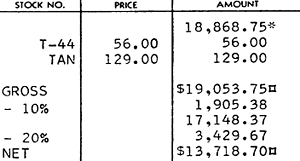
Usage example of the square lozenge as a suffix to mark (sub)totals.
(Mind the first position on the top similarly marked by an asterisk.)
IBM, 407 Accounting Machine, Manual of Operation; 22-5765-7 [5].
*****
Technical Notes
The IBM 026 Card Punch was introduced in 1949 (together with the non-printing, otherwise identical model 024). The IBM 024 and 026 featured BCDIC (BCD), Binary-Coded Decimal Interchange Code, as the character set. The IBM 029 Card Punch was introduced in 1964 together with the System/360 line of computers. The IBM 129 came in 1971 with the System/370. The IBM 029 and 129 featured EBCDIC, Extended Binary Coded Decimal Interchange Code, as the character set. Prior to the introduction of model numbers in the three-digits range, namely the IBM 129 Card Data Recorder, models 024, 026, 029 were referred to as 24, 26, 29.
Another way to get some print onto a punched card was the use of an interpreter, like the IBM 557 Alphabetic Interpreter introduced in 1954. The purpose of this machine was to scan a card already punched, to interpret the punch codes found in any of its columns, and to add human readable print onto the top edge of the card. As printing was achieved by a typewheel, an interpreted card is easily told apart from a card produced by a printing card punch. Here is the layout of the typewheel of the IBM 557:
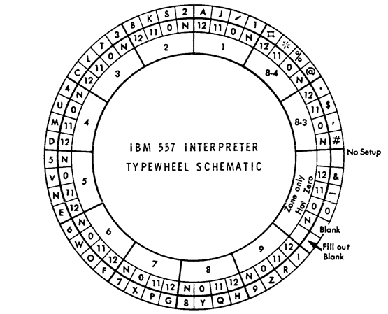
Schematic of the typewheel of the IBM 557 Alphabetic Interpreter.
The inner circles give primary punches and any additional zone punch codes (N = none).
IBM Reference Manual, 557 Alphabetic Interpreter; Dec. 1959.
Codes and character set as interpreted by the IBM 557 were the same as those used by the IBM 024 (non-printing) and IBM 026 (printing) card punches:
Print and punch codes as interpreted by the IBM 557 Alphabetic Interpreter.
IBM Reference Manual, 557 Alphabetic Interpreter; Dec. 1959.
Here's a specimen of the printing on an interpreted card
(by an earlier interpreter used by US forces in WW II):
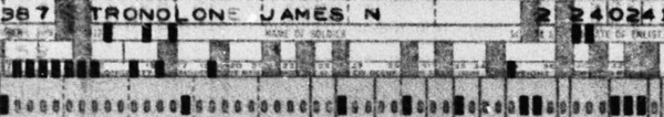
Top edge of a punched card with printing added by a card interpreter.
Image (aspect edited): The National Archives and Records Administration.
Finally, there was yet another machine which could print on a card, known as Dup/Print/Punch, a combination of a keypunch, interpreter, and reproducer. A post WW II version of this type of machine (there had been earlier models, as well) was the IBM 526 Printing Summary Punch (in the US forces known as Card Punch-Reader Interpreter RO-256/MYQ-4, compare the Operators's Manual). As the IBM 526 was a hybrid built around the 026 Card Punch, it may be expected to have performed similarly in printing. Compare the entry at the Columbia University Computing History website.