The Skiatron and Early Dark Trace CRTs
A glimpse of an alternative display technology.
It’s fairly well known how CRT displays made their way into computing, from WWII-era PPI (Plan Position Indicator) scan RADAR displays via Whirlwind, the Charctron display and the SAGE protype displays, seeing further applications in the TX-0, TX-2, and DEC PDP computers.
However, there may have been an alternative technology available, namely dark trace or scotophor CRTs. In contrast to the light-emitting light-on-dark phosphor CRTs, these drew their images, like the name suggests, in dark traces on a light, often backlit background. Coming at the designation P10, these tubes used tenebrescent minerals, like alkali-halide crystals, instead of phosphor, but could be controlled by the usual means of a cathode ray and deflection circuits. A notatable feature of these dark trace tubes was a non-volatile image, which gave them similar properties to E-Ink.
The basic effect of electron-opacity had been discovered by E. Goldstein in 1894, whith further research by R. W. Pohl following in the 1930s. A major drawback of this technology was the required cooling and heating for drawing and erasing the image. Due to the thermal masses involved, this resulted in rather poor update rates. A notable example had been developed by Telefunken, the Blauschrift-Röhre LB50, using heat, which was effected by applying electric current to a tungsten film on an additional, thin mica layer, only for erasing the image. (However, this still took 5 to 10 seconds, in which even the darkest of traces could be erased.)
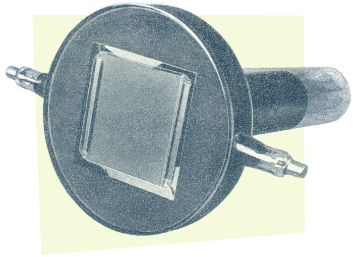
Ports on the left and right of the front of the tube connect to the tungsten film for image erasure.
Image: G. Wikkenhauser: ”The Skiatron or Dark Trace Tube”,
Electronic Engineering, Jan. 1948, p 22 (fig. 6). (edited)
Technically, free electrons in the alkali-halide crystals are displaced by the cathode beam and secondary emission electrons take up positions in the faults of the crystal lattice, vibrating at frequencies corresponding to certain wavelengths. And it’s this virbration, which causes the absorption of those wavelengths, resulting in dark traces on the semi-transparent crystal layer. The apparent color of the display is the complementary color of the absorbed wavelengths, pink for potassium chloride (absorbing the green ranges of the spectrum), or brown for potassium bromide (absorbing more in the bluish range.) Under the bombardment of light or heat, the electron holes in the crystal lattice are eventually closed again, with the screen reverting to its original semi-transparent state. However, in absence of such an irradiation, the excited areas of the screen will remain in the absorbent state, preserving the dark traces.
It was recognized at that time that much work would be required to achieve the necessary perfection. (…) The images received were not satisfactory mainly because of insufficient contrast. This was due to the fact that the traces remained on the screen too long, and disappeared only gradually. The time of disappearance of the trace is a function of the amount of the original discolouration, darker traces requiring a longer time, and to prevent blurring of successive pictures (which were transmitted at the rate of 25 pictures per second) it was necessary to limit the darkening to very faint traces.
Further, the contrast is weak in the picture because the dark discolouration dies away according to approxiamately an exponential function, and, of course, the human eye during one picture frame sees the integrated effect over the frame scanning time. Due to the fact that a dark trace is produced which fades away gradually, the contrast in the recieved picture is very low. (…)
However, this initial experiment proved that tubes of this description using extraneous illumination should be capable of providing sufficient screen illumination even for large projections.
(Wikkenhauser, G.: ”The Skiatron or Dark Trace Tube”, Electronic Engineering, Jan. 1948, pp 20–22, from which most the information provided here is drawn.)
Nevertheless, it was recognized that this technology lent itself to bright pictures and especially to large projection screens (something, Scophony, who had demonstrated their opto-mechanical scan 24×20" ES104 projection TV set at the Radiolympia exhibition in 1938, would have been fairly interested in.)

Image: G. Wikkenhauser: ”The Skiatron or Dark Trace Tube”,
Electronic Engineering, Jan. 1948, p 20 (fig. 5). (edited)
While a display for TV applications, which would provide a more square-wave function of persistence at 1/25 or 1/50 secs rates, remained still to explore, the technology saw applications in other areas during WWII, namely transient displays for oscilloscopes (see the image above) and applications where a long-duration, persistent image was favorable. Like large screen PPI displays for ground RADAR. One of the major advantages in these applications was not to the least that these — in contrast to fluorescent, light-emitting CRTs — could be viewed in ambient light conditions and, as already observed, could be projected onto even larger screens.
Wikkenhauser provides an image of a large screen Skiatron as used by the British Admiralty in WWII:
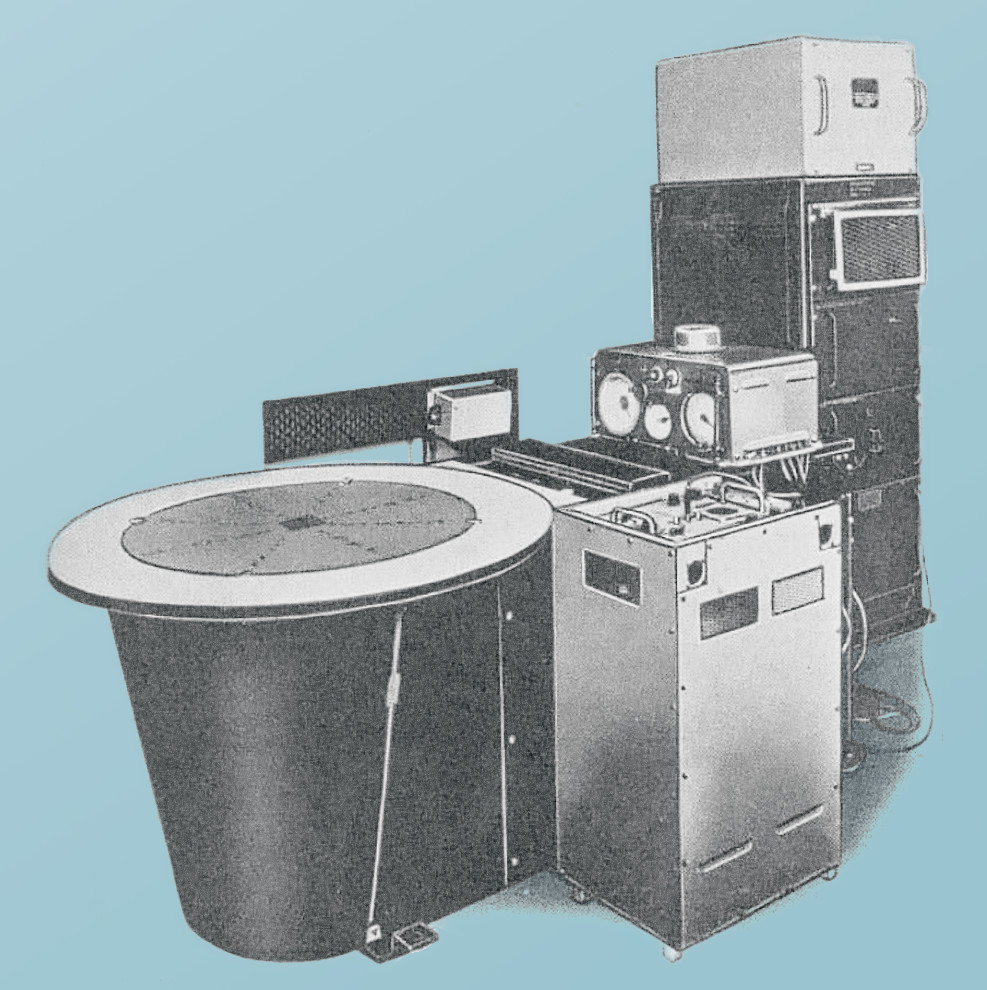
Image: G. Wikkenhauser: ”The Skiatron or Dark Trace Tube”,
Electronic Engineering, Jan. 1948, p 21 (fig. 3). (edited)
While this seems a bit unwieldy with its associated heating equipment, there are some remarkable features to this, like the planar, horizontal screen (something hard to accomplish with fluorescent CRTs, where the phosphor tends to separate as a fine powder falling down the tube and thus limitting the lifespan of the CRT severely), and its suitability for daylight operations.
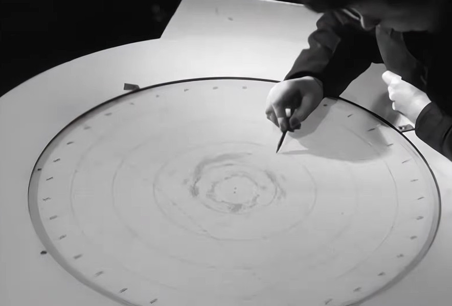
But there is more, as I stumbled upon the following T.R.E. film, “RDF to RADAR” from 1946, contemplating British war-time operations, which provides at 15:03 the following live images of a 1.5 meters Skiatron used as a PPI display for RAF ground RADAR during the war (the acronym “GCI” used in the commentary probably refers to Ground Controlled Interception):
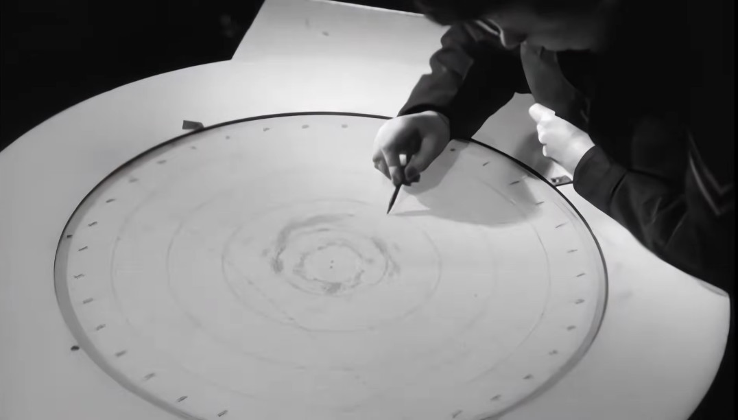
This is quite remarkable — especially for a projected image —, as we can here observe properties, which aren’t that dissimilar to fluorescent CRTs that were optimized for PPI purpose, like a live display with high update rates (we can clearly discern the moving radius of the face of the scan array) and a persistent image with quite a usable contrast.
Here’s a still showing the display:
P.G.R King and J.F Gittins provide the following assessment of the Skiatron in WWII in their 1946 IEE article “The Skiatron or Dark-Trace Tube” (articles and papers on the Skiatron and its characteristics continued to appear until araound the mid-1950s):
The Skiatron, or dark-trace tube, was developed to meet a radar requirement for a large-screen “black on white” picture with a persistence of several seconds. The present Skiatron consists of a magnetically focussed and deflected cathode-ray tube, with a screen consisting of a translucent micro-crystalline layer of potassium chloride. This screen is obtained by evaporation of the material in vacuum on to the tube face. An intensity-modulated scanning electron beam produces a picture by causing darkening in the areas bombarded. The picture is episcopically projected using external illumination from mercury-vapour lamps. Screen characteristics have been measured by a photo-electric cell and a recording galvanometer. It is shown that the intensity of coloration increases with excitation until a saturation value is reached. Coloration produced by a pulse of excitation decays in several seconds and is referred to as “transient,” while that produced by a series of pulse excitations, applied at intervals, may take several hours to decay and is therefore known as “persistent.” Increase of temperature reduces contrast but increases the decay rate. Decay rate also increases with illumination, from zero in the dark to a saturation value at about 5 000 ft candles. The overall efficiency of the screen increases with beam voltage. The decay rate of the persistent colour can be greatly increased by periodic electron bombardment at low intensity. The presence of impurities also increases the decay rate, but the effect is not permanent. Application of basic coloration theory to the Skiatron indicates that the persistent colour is due to ionic diffusion. The Skiatron is fairly successful for radar work but is unsuitable in its present form for television.
(King, P. G .R., Gittins, J. F: “The Skiatron or Dark-Trace Tube”, Journal of the Institution of Electrical Engineers, Vol. 93, Part IIIA, 1946, pp 171.)
Post-war, dark trace CRTs seem to have seen some use for storage oscilloscopes, as well as early civil flight RADAR (Wikkenhauser mentions an installation at the All-Weather Flight Center at Willington, Ohio, which was apparently then in planning.)
Provided that these featured the same properies, which were also preferable for early X/Y displays in computer application, this poses the question, why this wasn’t considered, especially given the daylight capabilities of these displays and that insights into German war-time developments, which had now become accessible, could have opened oportunities for further development. (Especially the use of electric erasure, as seen in the Blauschrift-Röhre with their integrated tungsten film, which had also seen use in RADAR applications, might have been interesting. Notably, we see them already described in Wikkenhauser’s paper of 1948.)
— Does anyone know why this hasn’t been considered? —
Finally, here is an image of an US-American Skiatron tube used for projection in RADAR applications:
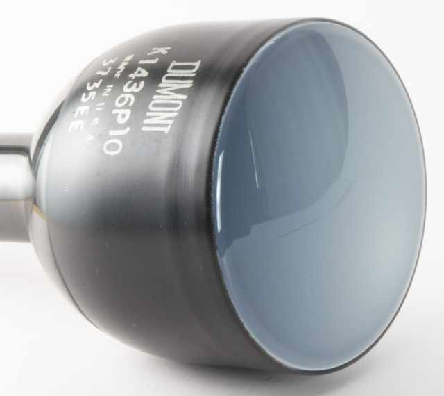
Image: lampes-et-tubes.info (copyleft).
PS: It may be worth noting that not all was lost for the cause of computing. Most importantly, the Williams-Kilburn tube, the first viable and fast random access memory device invented in 1946, shared a basic working principle. While utilizing a phosphor CRT, the Williams-Kilburn tube also relied on the electron wells caused by the secondary emission. On the Skiatron, these were responsible for the absorption of wavelengths and, thus, the visible traces. On the Williams-Kilburn tube, this local depletion of electrons is what is detected by the read cycle. So both the Williams-Kilburn tube and Skiatron relied in their functionallity on the secondary emission, rather than on the primary emission (which effects the light emission of visual phosphor CRTs). I have no idea whether or not any familiarity with the principles of the Skiatron furthered the invention of the Williams-Kilburn tube, but it’s still a noteworthy similarity.
Norbert Landsteiner,
Vienna, 2023-09-06 (amended)