Episode 10: Title Graphics
We rounding up our game by adding a nifty title screen. Since I did so already yesterday, we've a bit of time left to be spent on the principles. Also, I experimented a bit with enhanced video effects, the results of which ventures are conveyed at the end of this episode.
However, this is not the end of the story, since we're still lacking sound.
Extra Wide: 6 Digits Score Display / 48 Pixels Graphics
So, finally, we come to meet the famous 6-Digits Score Display, also known as Big Sprites, or 48-Pixel Display. It's the best we can do in "high" resolution on the Atari 2600: 48 pixels in a row, composed of the two player sprites (8 pixels each) replicated 3 times at an offset of 16 pixels ("close"). The two sprites will be mended together, forming a continous strip of 48 pixels (8 × 6). Nothing out of the ordinary, since the VCS and its TIA chip provide for that. Our job is now to change the bit-patterns for the two sprites on the fly, 4 times, just-in-time, with perfect cycle count.
Considering, there are 3 color clocks (pixels) rendered for each CPU cycle and storing a value at a zero-page address takes 3 of them, there are 9 pixels being rendered for any attempt to change any of the registers involved, while the sprites are just 8 pixels wide. *Hem*.
We may try anyway. Just wait for the first sprite actually being used and rewrite it, to be used for the 8-bit pattern after the next one (the second copy of the first sprite) and so on:
    (...)
    sta GRP0           ; set up first copy of player0
    (...)
    sta GRP1           ; set up first copy of player1
    (...)              ; first sprite begins to be rendered
    sta GRP0           ; rewrite it
    stx GRP1           ; rewrite this one
    sty GRP0           ; rewrite for 3rd copy
    st? GRP1           ; what register?!?
Holy Chip Die, Batman, we've run out of registers!
(Yes, here we do feel more like Robin than like being Batman.)
Unless the 6th sprite is exactly the same as the 4th one, there's apparently no way to do it. Moreover, we may be a bit too late anyway. So, how does Pitfall! and all those games manage to do this? At least, there are those 48-pixel scores on the screen to behold by everyone who cares to do so. What may be the secret, which is lying this openely before our very eyes?
As usual, the answer is provided in the Stella Programmer's Guide and in the creative use made of the information. The TIA has a somewhat obscure feature, meant to deal with multi-line kernels (where we spend two scan-lines in any iteration of the main display loop) and still maintaining accurate positioning. In fact, there are not just the registers GRP0 and GRP1 for the player graphics, but also a couple of shadow registers, named GRP0A and GRP1A, respectively. Every time, we write a value either to GRP0 or to GRP1, they are updated as well. By the means of registers VDELP0 and VDELP1 we may select, which of the two registers are to be used for the display, for each of the players individually. (There's also VDELBL for the ball, but none for the missiles.)
TIA Delay Registers (VDELP0, VDELP1, VDELBL)
| D0 | Meaning |
|---|---|
| 0 | no delay (use normal GRxx registers) |
| 1 | delayed (use GRxxA registers) |
Having set VDELP0 to 1, GRP0 actually serves as a buffer to GRP0A, and, having set VDELP1 to 1, GRP1 will serve as a buffer to GRP1A and the TIA will be using the A-registers to generate the display. The tricky (or obscure) part is, how and when the A-Registers receive their values. It's not what you think! They're updated vice versa:
- Each time, a value is written to GRP0, the value in GRP1 is copied to GRP1A.
- Each time, a value is written to GRP1, the value in GRP0 is copied to GRP0A.
The general idea behind this is that we will be writing values alternatively to the player graphics registers (GRP0, GRP1), as usual, but the TIA will be using the delayed A-registers. Here, on the other hand, we are especially interested in the buffering, since this provides two additional registers, where we can store any player graphics! Also, the buffering may help with tight timing constraints.
As a preparation for the following, we will want to set the two player sprites to 3 copies at normal size each, to be displayed at "close" distance, and instruct the TIA to use the A-register for each of them:
    lda #3             ; 3 copies, close
    sta NUSIZ0
    sta NUSIZ1
    lda #1             ; use delayed registers
    sta VDELP0
    sta VDELP1
And here it is, the 48-pixel sprite trick in all its glory (the base addresses of the 6 sprites are supposed to be set up in 6 16-bit pointers starting at GRTABLE, memory address GRHEIGHT is to be set up with the appropriate height value):
Player 0 has been set to pixel 123 (including horz blank) and Player 1
has been set to pixel 131.
[I.e., centered, starting at pixels 55 and 63 of the visible area.]
So the digits [sprites] begin at pixels 123, 131, 139, 147, 155, 163.

                        Cycles  Pixel    GRP0   GRP0A   GRP1   GRP1A

loop
    ldy  GRHEIGHT        ;+3  63  189
    lda  (GRTABLE),y     ;+5  68  204
    sta  GRP0            ;+3  71  213      D1     --      --     --
    sta  WSYNC           ;go
    lda  (GRTABLE+$2),y  ;+5   5   15
    sta  GRP1            ;+3   8   24      D1     D1      D2     --
    lda  (GRTABLE+$4),y  ;+5  13   39
    sta  GRP0            ;+3  16   48      D3     D1      D2     D2
    lda  (GRTABLE+$6),y  ;+5  21   63
    sta  TEMPVAR         ;+3  24   72
    lda  (GRTABLE+$8),y  ;+5  29   87
    tax                  ;+2  31   93
    lda  (GRTABLE+$A),y  ;+5  36  108
    tay                  ;+2  38  114
    lda  TEMPVAR         ;+3  41  123              !
    sta  GRP1            ;+3  44  132      D3     D3      D4     D2!
    stx  GRP0            ;+3  47  141      D5     D3!     D4     D4
    sty  GRP1            ;+3  50  150      D5     D5      D6     D4!
    sta  GRP0            ;+3  53  159      D4*    D5!     D6     D6
    dec  GRHEIGHT        ;+5  58  174                             !
    bpl  loop            ;+2  60  180

At the *, the value written to GRP0 does not matter. What does matter is
that this write triggers GRP1A to receive new contents from GRP1.  A "!"
indicates that that register is being used for displaying at that moment.
(Erik Mooney, “The scores / 48-pixel highres routine explained!”. [Annotations (in grey) by me, N.L.])
As may be observed, this is extremely tight regarding timing constraints. An iteration of the display loop takes 71 CPU cycles, "sta WSYNC" adds another 3 to them (74 in total) with just two cycles to spare (a scan line is completed over 76 CPU cycles). Moreover, the timing for writing to the GPRx registers is of uttermost concern, since we may easily miss one of them. It goes without saying that the graphics are to be aligned in memory towards the base addresses of the pointers, since any crossing of page boundaries will add another cycle, causing us to miss the right moment.
Here's an (my) alternative interpretation of the code, revealing, where the time sensitive stuff is actually happening and how values (here indicated as A...F) are propagated through the various registers:
                                GRP0   GRP0A    GRP1   GRP1A   TEMP  X  Y
loop
    ldy  GRHEIGHT        ;
    lda  (GRTABLE),y     ;
    sta  GRP0            ;   #-> A       E       X ====> X
    sta  WSYNC           ;---------------------------------------------hsync
    lda  (GRTABLE+$2),y  ;
    sta  GRP1            ;       A ====> A   #-> B       X
    lda  (GRTABLE+$4),y  ;
    sta  GRP0            ;   #-> C       A       B ====> B
    lda  (GRTABLE+$6),y  ;
    sta  TEMPVAR         ;                                       D
    lda  (GRTABLE+$8),y  ;
    tax                  ;                                           E
    lda  (GRTABLE+$A),y  ;
    tay                  ;                                              F
    lda  TEMPVAR         ;======================= 1st sprite GRP0A rendering
    sta  GRP1            ;       C ====> C   #-> D       B
    stx  GRP0            ;   #-> E       C       D ====> D
    sty  GRP1            ;       E ====> E   #-> F       D
    sta  GRP0            ;   #-> X*      E       F ====> F
    dec  GRHEIGHT        ;============================= last sprite rendered
    bpl  loop            ;

    #-> A .... value A is written to a register, now holding A
B ====> B .... value B is implicitly copied from one register to another
(As for visual content, we only care about blue values/states in GRP0A and GRP1A.)

       X* .... the last write to GRP0 is only to trigger the copy to GRP1A,
               the value actually written to GRP0 is of no concern.
The time sensitive instructions are starting at "lda TEMPVAR", when pixel 123 is rendered during CPU cycle 41. With this insight, we may venture to adjust the code for other positions as well. However, a centered position is exactly what we want for our title graphics, so we will be fine with this.
Extra Cycles: Implementing the Title Screen
For our title screen (or splash screen), we want something fancy. Not just a logo in the middle of the screen. Maybe, also some kind of variation, movement, action… We already have all the code for a bouncing ball and found an ultra fast way to display it. — Maybe we can squeece out some time of the code for an extra lookup and a store instruction?
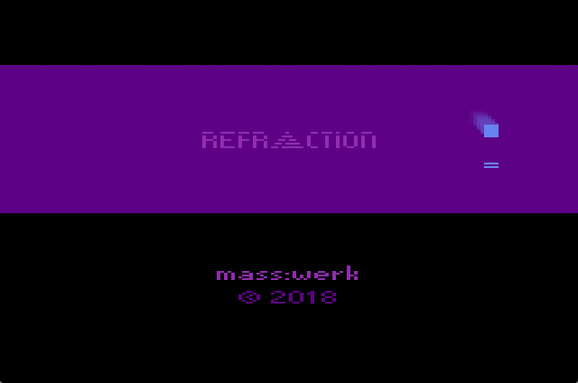
Our title graphics. The ball is bouncing behind the title accross the screen. While the upper boundary for the bouncing action is obscured and clipped by the top black area, the ball will bounce back up at the base-line of the logo graphics. The first few scan lines below this are showing a reflected image of the bouncing ball, when near this lower boundary.
We'll need 8 extra cyles to do this, and we'll need them right after the horizontal sync, since the ball is bouncing all over the width of the screen. (Meaning, we have to have it done and ready at the first visible pixel.) Also, we can't add this before the strobe of WSYNC, as there are just 2 cycles left and our code would spill over into the next scan line. However, we're just displaying static text and the base addresses for the bytes representing the graphics will always be the same. We won't need any pointers, basic indexed memory lookup will do fine for our purpose. By this, we gain 6 extra cycles, 5 of them before the time critical instructions start.
Three to go. By now, our code looks something like this:
loop
    ldy  SpriteHeight
    lda Data_0,Y
    sta GRP0

    sta WSYNC              ; h-sync, start counting ...
    (...)                  ; 5 spare cycles
    lda Data_1,Y
    sta GRP1
    lda Data_2,Y
    sta GRP0
    lda Data_3,Y
    sta Temp
    lda Data_4,Y
    tax
    lda Data_5,Y
    tay
    lda Temp

    sta GRP1               ; don't touch ...
    stx GRP0
    sty GRP1
    sta GRP0
    dec SpriteHeight
    bpl loop
Obviously, there's no need for the "tax" instruction, since we may now use "ldx Oper,Y" instead. Another 2 cycles, one to go. Can you see it? Probably not, since it is not there. Can we shuffle the code around? No. However, considering the workings of our sprite positioning routine, shifting the position of the graphics just a single pixel to the right, to pixel 56, will provide us the extra cycle (since Player1 will be rendered using a fine adjustment offset to the left).
****************************** Note to Diary ******************************
*                                                                         *
*  Whenever in need of an extra cycle, consider that HMOVE may provide    *
*  you with up to two cycles by moving an object to the left relative to  *
*  its 'natural' cycle position!                                          *
*                                                                         *
***************************************************************************
(intended cutout)
Et voilà, now we can do as follows:
LogoLoop
    ldy Spr48Height
    lda Logo_0,Y
    sta GRP0

    sta WSYNC
    lda (BlPtr),Y          ; (5) load ball data
    sta ENABL              ; (3) and send it to TIA
    lda Logo_1,Y
    sta GRP1
    lda Logo_2,Y
    sta GRP0
    lda Logo_3,Y
    sta Temp
    ldx Logo_4,Y
    lda Logo_5,Y
    tay
    lda Temp

    sta GRP1
    stx GRP0
    sty GRP1
    sta GRP0
    dec Spr48Height
    bpl LogoLoop
The construct will be going into a kernel routine of its own (in Atari 2600 terms, kernel is not just used for the visual payload of a TV frame or a field, but more often for the entire code for rendering a screen), much like the one we already did for the playfield. The two kernel routines are completely independent, apart from the frame counter, which is shared to provide a random seed for the game. We'll check the Select console switch and the controller buttons and change to the game kernel, if either is active. In the game kernel, we check for Reset and jump to the start of our program, by this reentering the title screen.
Other, there isn't much to be told. There are two further "big sprites" on the title screen, one reading "mass:werk" (since we're proud of our accomplishments) and the other the year. We may put the original code in a subroutine and use the pointers, however, setting up the pointers is about as much code as the rendering routine itself and takes the better part of a scan line to run. So we're easier off, at the same results, by just copying the code above and replacing the intsructions for displaying the ball graphics by a sequence of four NOPs (2 cycles, each). A series of tiny, empty loops provide for the vertical separation. (Also, we do some math in the assembler for vertical positions for both NTSC and PAL instances, relative to thirds of the screen height.)
That's all. — Don't miss the live experience!
Extra Bits: What is the Best Image Resolution on the VCS?
Before I did this, I happened to explore the capabilities of VCS graphics. What is the best we can do?
In fact, we're not limited to just 48 pixels of a single color, we may add to this by displaying interlaced graphics at alternating frames. By this we may gain some resolution (similar to antialiasing) and emulated halftones!
For the matter of an experiement, I produced the following 96 pixel wide graphic of the VCS (a drawing from the patent application) and used the odd vertical columns for one frame and the even ones for another frame. (No attempt was made to fine adjust pixels for extra effects.) Since the pixels produced by the TIA are about double as wide than high, the overall aspect ration of the image will be maintained.
Here is the source image from the patent drawings:

Source image (96 pixels wide, 2 × 48).
Rastered by threshold to produce two images consisting of either just even columns or odd ones.
This is what we get in the "Stella" emulator using the default video settings (no TV effects):
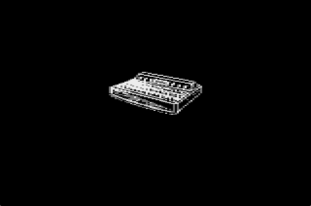
“Stella by Stella” — OpenGL, Default video settings.
Two frames of interlaced video drawing 48-pixel graphics (superimposed stills).
And here using the "RGB" emulation settings:

“Stella by Stella” — OpenGL, "RGB" video settings.
And, finally, using the "Composite" emulation settings:
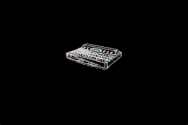
“Stella by Stella” — OpenGL, "Composite" video settings.
Is it good enough for an effect? That may be open to debate. Mind that this is not the kind of interlaced video TVs were intended for, since we're lacking the drop by half a scan-line between fields. As for modern use, it clearly depends on the indivdual video settings and emulators.
For a comparison, this is what we may get with Javatari's video filters:
Javatari.js, CRT filter mode "3".
(While extremly blurry, it really resembles an image of a resolution higher than the VCS can provide.)
In the end, I opted for hand drawn pixel typography.
In case you missed out on it previously, here's the live demo.
▶ Next: Episode 11: Color TV Systems
◀ Previous: Episode 9: Scores!
▲ Back to the index.
April 2018, Vienna, Austria
www.masswerk.at – contact me.
— This series is part of Retrochallenge 2018/04. —