Episode 2: Stars & Sync
We start our efforts on the code with amazing news: In case we succeed, we may have a realistic chance that the code may be run on the only operational PDP-1 existing, the restored PDP-1 at the CHM. Reason enough to get going…
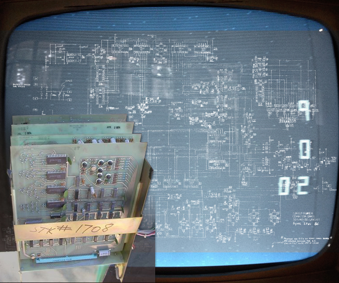
Computer Space background stars and PCB stack.
(Screenshot by Ed Fries, 2015; photo of PCB stack, two-players version: KLOV;
schematics of single-player version of the Sync-star board: Nutting Associates, 1971.)
The single-player version of Computer Space (there's a one-or-two-player version too, the origin of which is somewhat subject to debate) consists of 3 PCBs: The Sync-star board, the memory board and the motion board. The first of them the Sync-star board is the only board that can be run without the other twos providing — as may be guessed from its name — the basic synchronization (required to feed a video signal to the TV) and the background starfield.
This may be a good starting point for our project, too. We'll set up a basic program with main loop to be executed for each frame and populate this with a starfield to be used as a backdrop for the game. Let's have a closer look at the background stars of Computer Space:

The background stars of Computer Space.
(Image: Computer Space Simulator by Mike "Moose" O'Malley.)
Oops — Lots of stars! A rough estimate is about 250 of them. (Bet, it's 256?) In comparision our reference application for the PDP-1, Spacewar!, has about 40 of them concurrently on the screen. As already mentioned, display commands are our major bottleneck and we simply cannot afford that many dots to be drawn each frame. So we may have to think about something different, involving less of these celestial blips.
The pattern of the background stars of Computer Space is always the same, it's hard-wired on the board. We enjoy a bit more of freedom here, and we may want to go with a random starfield that is set up individually at the beginning of each game. And maybe, we'll also add a little extra.
But before we actually start, we'll have to spend some words on the Macro assembler. (This episode may be rather extensive, but as we go along, we'll be able to reduce our explanatory comments quite a bit.)
The Macro Assembler
MIT's Macro assembler has its root on the TX-0, and even the output format is similar on the PDP-1. It's a straight forward two-pass assembler and we may provide the most essential rules in just a few lines:
- The very first line gives the title of the program (to head each page of any printout).
- Everything of up to 3 characters at the beginning of a line followed by a comma is a label.
- Something up to 3 characters followed by an assignment (
=) is a symbol. - Symbols can be declared at any place, but only once. Any redefinition is an error.
- Anything of 4 characters or more is either a pseudo-instruction (setting a mode of the assembler) or the name of a macro. Only the first 4 characters are significant and names may be abbreviated.
- A macro starts with the keyword "
define", followed by the name and an optional parameters list, and ends with the pseudo-instruction "terminate". - Another type of symbols are assembler variables, they consist — like other symbols (labels, etc) — of up to 3 characters, at least one of them is marked by an overstroke.
The modern C-version uses a backslash (\) as prefix instead.
(Variables are managed by the assembler and may be used similar to a labeled memory location. The symbol has to be marked as a variable at least once in the source code.) - Constants are set in parentheses "
( ... )". Only the opening parenthesis is required. (I've never seen a closing one in any source.) Constants are managed by the assembler, like variables. If a constant is used more than once, there's still only one memory location used. - The pseudo-instructions "
constants" and "variables" reserve the respective memory locations in place. - Anything in a line that is not a starting label or a pseudo-instruction is simply added up and the respective value is used as the instruction word.
- Line endings and tabs are synonymous.
- There are a few special characters:
- A dot (
.) denotes the current memory location (PC). - The character "
R" denotes the relative offset from the starting position of a macro. - An expression immediatly followed by a slash (
/) sets the PC to the respective value. - Any other occurrence of a slash (
/) starts a comment. - Finally, the pseudo-instruction "
start" (followed by an optional start address) marks the end of a block or of the program.
As for the instruction codes, we'll discuss them, as we'll encounter them. However, I've prepared an overview of the PDP-1's instruction list and there's also a short version of it provided in a tab at the bottom right of this page, expanding for quick reference.
▶ Open in a new tab/window: PDP-1 Instruction List
A PDP-1 Assembler Code Boilerplate
Let's start with the basic layout of any PDP-1 macro-code. Most programs start at address 4 — for a reason:
The PDP-1 has a Sequence Break System (by moderns banally called a system interrupt). In case a Sequence Break occurs, the PDP-1 dumps th contents of the accumulator (AC) in address 0, the contents of the program counter (PC) in address 1, and the contents of the in-out register (IO) in address 2. Then it executes the instruction currently in location 3. Thus the first 4 addresses (0...3) are reserved for the purpose of the Sequence Break System and the first location available to our program is address 4.
Lets have a look at basic Sequence Break handling (this is the one found in Spacewar!):
/routine to flush sequence breaks, if they occur.

sbf,	tyi		/ reset console typewriter
	lio 2		/ restore io (fom contents of addr. 2)
	lac 0		/ restore ac (fom contents of addr. 0)
	lsm		/ leave sequence break mode
	jmp i 1		/ resume: indirect jump to address in loc 1
Here, "sbf" is the first example of a label (it's 3 characters and followed by comma), marking the location of instruction "tyi". This one resets the internal state for the communication with the console typewrite (Soroban), because, it's 100:1 that — once again — someone couldn't resist to tap a key. Then we restore the contents of the registers from where the Sequence Break System has dumped them, instruct the machine to leave the break-mode (because our interrupt handler has finished) and pick up, where we were interrupted by an indirect jump to the value in address 1. — The most simple code to just ignore the break.
Of course, we've to insert a jump vector to our sequence break routine at address 3. Putting it all together, we arrive at the following basic layout:
title of my great program

/insert some macro definitions here?

/set program counter to 3 and insert jump vector to squence break routine
/followed by a jump to the main program (here a0) at 4

3/	jmp sbf		/ ignore seq. break
	jmp a0		/ start addr, jmp to a0

/routine to flush sequence breaks, if they occur.

sbf,	tyi
	lio 2
	lac 0
	lsm
	jmp i 1

/maybe some other macros and parameter definitions?

/main program

a0,	....		/snip

/insert constants and variables, end of program

	constants
	variables

	start 4
Pretty easy. If we risk a further look at addr. 3, this is what the assembler produces as an output listing:
    8 00003             3/	jmp sbf		/ ignore seq. break
      00003 600005
The first line gives the line number and the current location (PC) followed by the source code, the second line the address and the value generated for it. As we may see, it just added up the instruction code for "jump" (octal 600000) and the value represented by the label "sbf" (here "5", since the jump to "a0" occurs at addr. 4 and our label "sbf" thus follows at 5). That's it.
Setting Up Some Stars
Time to actually venture into our program — let's set up some stars. For this it may be nice to know something about the display command (dpy) and how screen coordinates are transmitted.
Actually the command "dpy" is a subcode of the in-out transfer group "iot". It's basic instruction code is "720000", where the least significant triplets encode the target device or port. In the case of the "dpy" instruction it's 720007, or — as the Macro assembler defines it including the i-bit — 730007. We'll see in a moment why.
Remember the Sequence Break routine and the instrcution for resetting the console typewriter? This honorable device, named Soroban, was a glorified IBM Model B electric typewriter put on steroids by Soroban Engineering of Melbourne, FL. This "very intricate mechanical marvel" (© CHM) remoted keypresses by the help of selenoids and was the only standard peripheral equipment that came with the PDP-1, besides the iconic DEC-chair.
Now, the mechanism was known to be, as mentioned, intricate, to times even flaky, and every now and then a printout would stop. What to do? Simply press the last letter printed and the process would resume! (Thanks to Ken Sumrall from the PDP-1 Restoration Team for the story!) — What may we learn from this? There's a full-fledged echo communication going on between the PDP-1 and any of its peripheral devices, with buffer registers and checks. And even more, the communication is fully asynchronous.
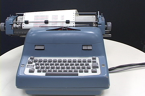
The Soroban console typewriter.
(CHM, Catalog No. 102664302.)
On the side of the CPU — and, that is, the programmer — all this asynchronous control flow is abstracted into a single, universal completion pulse. And that is, what is controlled by the i-bit in conjunction with the in-out transfer commands. (This is an example of the marvel of computer engineering that is the PDP-1: Embedding a still simple and easy to use CPU into a system of memory and I/O control circuitry that is at least as complex as the machine that is facing the programmer by abstracting its complexity into an asynchron access scheme that is as simple as a single bit.)
The control of asynchronous I/O is done by setting bits 5 (i-bit) and bit 6. Generally, setting the i-bit results in a blocking operation by requesting a completion pulse from the I/O device and immediately halting to wait for it (in case of the dpy command this would occur 45 microseconds later), or just fire the command and continue (hoping the best).
A fully controlled asynchrounous communication can be established by the help of bit 6: If this XOR-ed with the i-bit is hi, a completion pulse is requested anyway, even, if the CPU does not block. Hence, we may (and have to) wait at any other time for the completion pulse by the "ioh" instruction.
So, there are the following viable options (mind that "dpy" is defined in the assembler including the i-bit):
i-bit  bit 6      effect       display command (in Macro)
  1      0        block             dpy
  0      0       no wait            dpy-i      (i: 10000)
  0      1       request cp         dpy-4000

sequence continue-&-request-cp ... wait:   dpy-4000 .... ioh
So, that we know this, how are coordinates transferred? By the means of AC (x) and IO (y). Just load those values into the respective registers and fire your "dpy" command. Only the most significant (highest) 10 bits are significant. (Using this format, we've established a fixed point fractional coordinate system for our game, already.)
Just for fun, we'll use a single 18-bit word to store the 2 coordinates. This may give a precision of just 9 bits, but we'll just assume the least significant bit being zero, since, we do not want to have any touching stars, anyway.
We start by declaring a symbol for the number of stars (we may decide to change this later), and then reserve a bit of space for the coordinates' table, a word per star:
/subroutines for background display

nos=77 	/number of stars

/table of stars coors (nos words, 9 bits x and 9 bits y)
bst,	. nos/
The label "bst" (background star table) now points to the first address of our table and the expression ". nos" adds the value of symbol "nos" to the current value of PC and reassignes it to this new vale. Thus, the next instruction will be assembled after a gap of nos (octal 77) locations.
Now, let's come to business. We'll need a random number generator and we'll steal our's recklessly from Spacewar!. (It may have been unique to Spacewar! or it may have been some kind of common code, anyway.) It's the macro definition "random", scrambling and modifying the bits in location "ran" (we'll have to declare this label) and also leaving the new random number in AC:
define random
	lac ran			/ load value of loc. ran in ac
	rar 1s			/ rotate ac right one bit
	xor (355670		/ xor ac with constant 355670
	add (355670		/ add constant 355670 to ac
	dac ran			/ deposit ac in loc. ran
	term			/ terminate (abrev.)

ran,	0			/ random number

/setup (nos random coors starting at bst)

bsi,	dap bsx			/ deposit return address
	law bst			/ load adddress of label bst into ac
	dap bsc			/ deposit ac in address part at label bsc
bsl,	random			/ get a new random number
bsc,	dac .			/ store it in current loc of st
	idx bsc			/ increment value in bsc, leave it in ac
	sas (dac bst+nos	/ is similar to (dac + bst + nos) ?
	jmp bsl			/ no, jump to bsl
bsx,	jmp .			/ return
The entry point to our subroutine is at label "bsi". That is, we are expected to call this by the instruction "jsp bsi". But how does a jump to subroutine work, without a CPU stack? Were to put the value of the return address? The PDP-1 puts it simply into AC and it's our job to take care of it. We'll use the instruction "dap" to just overwrite the address part (bits 6–17) of the target location with the contents of AC. The target is here the instruction "jmp ." at label "bsx". We're encountering here two conventions that are totally arbitrary: 1) a dot (.) as the lone address part of an instruction indicates that the address will be fixed up later (so, anything pointing to itself is a candidate for fix-up), and 2) all labels of a subroutine or task will start with the same character(s) and the label of the return instruction will end in "x".
(Note: There's also a practical aspect to using a dot (".") for the address part of a jump instruction that is to be fixed up: If we fail for some reason to set the return address, the machine will loop at this jump instruction to itself, thus identifying by the console lights, where we erred. If we left this blank, we would jump to location 0, regardless from where we came.)
The instructions "law" (load the literal value in the address part into AC, as opposed to lac loading the contents of the location provided in the address part) and "dap" (deposit AC in address part only) set up the address part of the location labeled "bsc" to the first address of our coordinates table.
Label "bsl" marks the start of our working loop, where the code of macro "random" is inserted in place. At the end of this macro, the newly generated random number is still in AC, and we deposit it in the location the address part of the "dac" instruction at label "bsc" is currently pointing to. — We've just stored our first coordinates!
Then the instruction "idx bsc" (index) increments the value in "bsc", in order to point to the next address in our table. As a side effect, the incremented value is also left in AC. So we may compare it to the last address (bst+nos) we have to vist. Since "bsc" also contains the instruction code for "dac", we'll compare it to the constant expression "(dac bst+nos". Instruction "sas" skips the next instruction, if the value is equal to the one in AC. If not, we've another iteration of the loop to do and jump back to "bcl". If we're done, the instruction "jmp bsl" will be skipped and we'll finally reach our fixed-up jump to return at label "bsx".
We may observe that this kind of code is notoriously self-modifying. It's true that we could have used some labeled pointers and indirect addressing instead, but this way we would have lost some precious instruction cycles for the additional memory lookups. However, this kind of code used to be common praxis.
Phew! — to make standard tasks a bit simpler, there's a set of common macros that we may use to substitute some of our instructions, generating the same code as above:
define initialize A,B
	law B
	dap A
	term

define index A,B,C
	idx A
	sas B
	jmp C
	term

/setup (nos random coors starting at bst)

bsi,	dap bsx				/ deposit return address
	init bsc, bst			/ deposit first addr of bst in bsc
bsl,	random				/ get a new random number
bsc,	dac .				/ store it in current loc of st
	index bsc, (dac bst+nos, bsl	/ increment bsl, repeat at bgl for nos times
bsx,	jmp .				/ return
We may observe that macros may take parameters. Parameters are upper-case and unique to individual macro definitions. Especially the makro "index" is quite versatile as it combines the count-up of loops with a condition to check the iterated value against a terminating expression. (Think of the the second and third part of a C-loop combined in a single pseudo-instruction.)
Displaying the Stars
We're still missing a routine to display our preciously defined stars. Here it is:
/display background stars (displays every 2nd frame only)

bg,	dap bgx				/ deposit return address
	isp bgc				/ increment bgc, skip on positive
bgx,	jmp .				/ return
	law i 2				/ load -2 into ac
	dac bgc				/ deposit in bgc to reset frame counter
	init bgl, bst			/ init bgl to first addr of stars table
bgl,	lac .				/ get coors of next star (x/y)
	cli				/ clear io
	scr 9s				/ shift low 9 bits in high 9 bits of io
	sal 9s				/ move remaining 9 bits in ac in high part
	dpy-i				/ display a dot at coors in ac (x) and io (y)
	index bgl, (lac bst+nos, bgl	/ repeat the loop at bgl nos times
	jmp bgx				/ return

bgc,	0
The first instruction is again the obligatory disposal of our return address. The next 4 instructions are dealing with displaying the stars every second frame only. The reason for this is the built-in brightnesses of the Type 30 CRT not really scaling well, also we may not want to spend every frame on the background display. (That is, we'll have slightly longer frames displaying the stars, followed by a slightly shorter frame skipping the display routine.) Thanks to the afterglow of the special long sustain phosphor of the Type 30 CRT the stars will be still visible, hopefully flickerfree (at least on the real machine), but they will be visually pushed back into the background.
(Woa — another Spacewar!-trick!)
To achieve this, we increment the value in the location labeled "bgc" (background counter) using the instruction "isp". This one is like "idx", which we've seen before, but also skips the next instruction, should the new vualue be a positive one. If not (i.e., it is negative), we immediately exit at "bgx". If it was positive, we load the literal value -2 into AC by the instruction "law i 2" (the i-bit here denotes a negative vale) and store this for the next call in "bgc". (The value in "bgc" will thus alternate after the increment between -2+1=-1 and -1+1=0.)
The insertion of macro "initialize" (short "init") sets up the address part at "bgl", the start of our display loop, to the first addres of the stars table (bst). The "lac" at "bgl" loads this 18-bit value into AC. "cli" clears IO to zero in preparation for the next steps. These are all about splitting these 18.bit word into two 9 bit values at the high end of AC and IO:
The PDP-1 has some very versatile rotate and shift instructions, micro programmed in a single shift group. While the op-code of the instruction indicates the kind of rotation or arithmetic shift and its direction, the lower 9 bits provide the number of bit-positions by which the value is to be moved. More precise, it's the number of hi-bits, as in 1, 3, ... 777. The Macro assembler provides for this a range of handy symbols, as in "s1", s2, ... s9.
Instruction "scr 9s" (shift combined registers right) combines AC and IO into a single 36-bit register and shifts its contents right by 9 bits, the maxiumum amount. Now, we've moved the lower part of AC into the highest position in IO and the remainder is now in the lower 9 bits of AC. "sal 9s" is the reverse shift to the left by 9 bits, but now on AC only, restoring the high-part of AC.
Now we're finally ready to display the star: Should we wait, or should we go (i.e., fire and forget)?
With a coarse look at our code, we're pretty sure that we pass more than 50 microseconds between display commands and opt for go, as in "dpy-i".
Follows the increment of the loop, same as in the setup routine, and, if we terminately fall through, we're jumping to the return at label "bgx".
Some Final Enhancements
By this, we've a static background display, just like the one of Computer Space, but with a little fewer stars. But, what about burn-in? The Type 30 CRT Display is precious equipment, even more now than then! We really should add some animation. We're yet undecided on the kind of animation or movement we'll want to apply for the stars, just scrolling them slowly around (like in Spacewar!), or, maybe, even some kind of parallax effect, relative to the movement of the player's rocket? (You'll bet on the latter!).
In order to do so, we add two further labeled locations at the end, namely "bgh" and "bgv" (for horizontal and vertical offsets, respectively) and add them to the coordinates.
Here, we encounter another essential macro, "swap". This swaps the values in AC and IO by rotating them as a combined 36-bit register twice by 9 bits (making 18 bit positions or a full word length in total). By this we get our final version of routine "bg":
define swap
	rcl 9s
	rcl 9s
	term

/display background stars (displays every 2nd frame only)

bg,	dap bgx				/ deposit return address
	isp bgc				/ increment bgc, skip on positive
bgx,	jmp .				/ return
	law i 2				/ load -2 into ac
	dac bgc				/ deposit in bgc to reset frame counter
	init bgl, bst			/ init bgl to first addr of stars table
bgl,	lac .				/ get coors of next star (x/y)
	cli				/ clear io
	scr 9s				/ shift low 9 bits in high 9 bits of io (x)
	sal 9s				/ move remaining 9 bits in ac in high part (y)
	add bgv				/ add vertical offset
	swap				/ swap contents of ac and io
	add bgh				/ add horizontal offset
	dpy-i				/ display a dot at coors in ac (x) and io (y)
	index bgl, (lac bst+nos, bgl	/ repeat the loop at bgl nos times
	jmp bgx				/ return

bgc,	0
bgh,	0
bgv,	0
Syncing Frames
Now, it's time for the main loop. The PDP-1 is built for realtime, but it is actually missing a major provision for this: the system clock. — So how may we sync our frames? Bet, we'll do it by a delay loop.
We'll declare a budget of instructions and — as our program will grow more complex — subtract certain amounts per task from it. Any remainder will be spent in a delay loop. And while there is no app for this, there's still another macro.
define count A,B
	isp A
	jmp B
	term
This will count up a negative value in A towards zero. If finished, we fall through at the exit, else we'll jump to location B to iterate. A quick look at the instruction list tells us that we'll spend 3 cycles per iteration.
And here is our main loop, currently just calling the background subroutine each frame:
/start a new run

a0,	jsp bsi				/ initial setup of bg-stars
	dzm bgh				/ reset offsets of stars to zero
	dzm bgv

/main loop

fr0,	load \ict, -4500		/ initial instruction budget (delay)

	jsp bg				/ display background

	count \ict, .			/ use up rest of time of main loop
	jmp fr0				/ next frame
At the start of the main program, at label "a0", the very label we jumped to at location 4 (our start address) calls the setup routine for the background. Also, we reset the contents of the vertical and horizontal offsets zo zero (instruction "dzm").
Label "fr0" marks the start of our frame, where macro "load" sets up the initial instruction count. Here is its definition:
define load A,B
	lio (B		/ load B as a constant into IO
	dio A		/ deposit IO in loc. A
	term
(Again, this a macro from the common "macro fio-dec system".)
The value (-4500 = 7,104 instructions = 35,520 microseconds) is quite arbitrarilly chosen (and may be adjusted later).
Inside this loop, we call the background routine ("jsp bg") and spend our time in the delay loop ("count \ict, .", expanding to "isp \ict" and "jmp .", where the dot denotes the insertion point or beginning of the macro, the very instruction "isp \ict").
You may have noticed the backslash in front of "\ict" — yes, this is our first assembler variable. It is managed like any labeled address, but it's address will be determined by the next occurrence of the pseudo-instruction "variables".
The Code, So Far
ironic computer space  0.01  nl 2016-10-12

define initialize A,B
	law B
	dap A
	term

define index A,B,C
	idx A
	sas B
	jmp C
	term

define swap
	rcl 9s
	rcl 9s
	term

define load A,B
	lio (B
	dio A
	term

define setup A,B
	law i B
	dac A
	term

define count A,B
	isp A
	jmp B
	term

define random
	lac ran
	rar 1s
	xor (355670
	add (355670
	dac ran
	term


3/	jmp sbf				/ ignore seq. break
	jmp a0				/ start addr, jmp to a0

ran,	0				/ random number


/routine to flush sequence breaks, if they occur.

sbf,	tyi
	lio 2
	lac 0
	lsm
	jmp i 1


/subroutines for background display

nos=77 	/number of stars

/table of stars coors (nos words, 9 bits x and 9 bits y)
bst,	. nos/

/setup (nos random coors starting at bst)

bsi,	dap bsx				/ deposit return address
	init bsc, bst			/ deposit first addr of bst in bsc
bsl,	random				/ get a new random number
bsc,	dac .				/ store it in current loc of st
	index bsc, (dac bst+nos, bsl	/ increment bsl, repeat at bgl for nos times
bsx,	jmp .				/ return


/display background stars (displays every 2nd frame only)

bg,	dap bgx				/ deposit return address
	isp bgc				/ increment bgc, skip on positive
bgx,	jmp .				/ return
	law i 2				/ load -2 into ac
	dac bgc				/ deposit in bgc to reset frame counter
	init bgl, bst			/ init bgl to first addr of stars table
bgl,	lac .				/ get coors of next star (x/y)
	cli				/ clear io
	scr 9s				/ shift low 9 bits in high 9 bits of io (x)
	sal 9s				/ move remaining 9 bits in ac in high part (y)
	add bgv				/ add vertical offset
	swap				/ swap contents of ac and io
	add bgh				/ add horizontal offset
	dpy-i				/ display a dot at coors in ac (x) and io (y)
	index bgl, (lac bst+nos, bgl	/ repeat the loop at bgl nos times
	jmp bgx				/ return

bgc,	0
bgh,	0
bgv,	0


/start a new run

a0,	jsp bsi				/ initial setup of bg-stars
	dzm bgh				/ reset offsets of stars to zero
	dzm bgv

/main loop

fr0,	load \ict, -4500		/ initial instruction budget (delay)

	jsp bg				/ display background

	count \ict, .			/ use up rest of time of main loop
	jmp fr0				/ next frame


/insert constants and variables, end of program

	constants
	variables

	start 4
Meanwhile, we've also prepared and set up our in-browser emulation (HTML5/JavaScript). We decide to render the screen at 640 × 640 pixels, so that we reveal plenty of detail in a format that should still fit most screens:
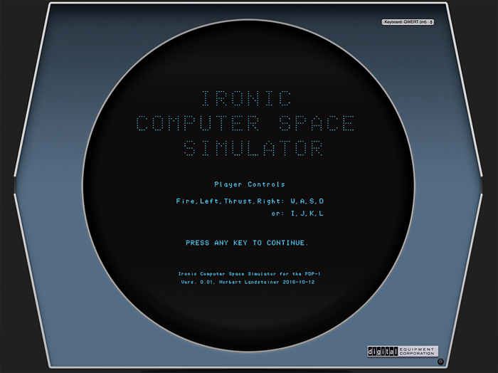
Our trusty emulator set up to run ICSS, head over to www.masswerk.at/icss/.
And this is what we get (see www.masswerk.at/icss/):

The background starfield.
That's all for this post.
▶ Next: Episode 3: Rocketry — Or, Fly Me to the Moon Stars
◀ Previous: Episode 1: Platform Considerations
▲ Back to the index.
2016-10-12, Vienna, Austria
www.masswerk.at – contact me.
— This series is part of Retrochallenge 2016/10. —