Episode 3: Rocketry — Or, Fly Me to the Moon Stars
In 1971, there was still a realistic, while rather exclusive, chance to go to the Moon. Not so today. — Therefor we humbly head for the stars, in stead. What will we need for this? A rocket, in the first place.
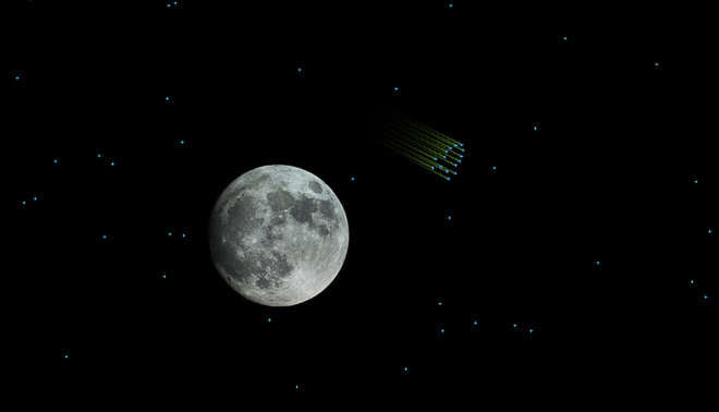
Going for the Moon Stars.
Maybe the most important part of Computer Space — and maybe every video game that is not rendering a first person perspective — is the player's representation on the screen. In the case of Computer Space it's a rocket-like spaceship. Famously, the layout of the rocket is traced out on the PCB generating the moving objects (the memory board), and so it is in the schematics.
There are 4 discrete positional layouts to represent the ship at any of 4 angles in half a quadrant:
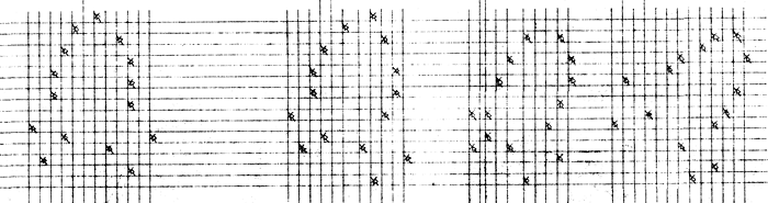
Computer Space: Schematics and layout of player's rocket. (Nutting Associates, 1971)
A closer inspection reveals that there's no straight angle in this. Rather, the ship is always slightly at an angle and even a little skewed. While pratically this may have saved the circuitry required for another position, on the screen we enjoy the impression of the ship always drifting a bit, which adds much to the charms of the game.
As we already noted in our platform considerations, we won't be able to reproduce this on the PDP-1, because of the afterglow of the Type 30 CRT Display and the need for a rather seamless motion arising from this. Just rotating the ship as sketched in the schematics to a straight angle won't do, since then we'd still lack a symmetric outline. After some tinkering, we eventuall arrive at a representation that is close in features to the average outline and also matches the dots to some unit grid.
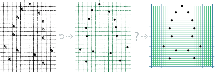
Finding the outline for our spaceship.
And here are the coordinates (top down), the respective differantials, and the differential offsets as sums of the discrete values 1, 2, and 4 (we'll see soon why):
 x, y        diff.        components

 0, 0        0,  0          0,    0
 3, 3        3,  3        2+1,  2+1
 7, 5        4,  2          4,    2
11, 6        4,  1          4,    1
15, 5        4, -1          4,   -1
20, 9        5,  4        4+1,    4
22, 3        2, -6          2, -4-2
26, 6        4,  4          4,    4
The way to seamlessly rotate an outline, as pioneered by Steve Russell and Spacewar!, is to calculate the unit vector (sine/cosine) of the rotational angle, scale it to the unit of choice and have a drawing routine that advances form bow to stern and displays each of the dots that are making up the outline. Since our outline is symmetric, we just encode one side, adjust some of the components of our matrix and repeat for a second pass to generate the other side of the shape.
Spacewar! features configurable outlines (encoding 5 leteral and/or downwards movements, a code to alternately store and restore the drawing position — think of fins —, and one to mark the end of the outline-encoding). First, this codes had been interpreted, but soon Dan Edwards came up with an ingenious out-line compiler (one of the first JIT compilers in history) that gave the program a decisive boost in runtime, freeing the computational resources for gravity calculations while maintaining a flickerfree display. (See "Inside Spacewar!", Part 4 for details.)
The product of this outline compiler is a procedural sprite — and this is also, what we're going for. Since we're not interested in configurable sprites, we'll directly code it by hand. And this is, how we move around in our grid:
direction           y               x

sternwards       - cos            + sin
outwards         + sin*           + cos*
inwards          - sin*           - cos*

*) sin* and cos* complemented for second, mirrored pass.
Having a look at our differential offsets, we observe all sorts of values from 1 to 6 in our table. As a compromise in costs of setting up the values and costs in repeated calculations, we settle for the three most frequent offsets that may also be used to produce the other ones: 1, 2, and 4. (Coincidentally, these are also powers of 2!)
But, first we need a sine-cosine routine. As did Steve Russell and Spacewar!:
« Russell, never one to "do something" when there was an alternative, begged off for one reason or another. One of the excuses for not doing it, Slug [Steve Russell; N.L.] remembers, was "Oh, we don't have a sine-cosine routine and gee, I don't know how to write a sine-cosine routine..." Then Alan Kotok came back from a trip all the way to Maynard (DEC headquarters) with paper tapes saying "All right, Russell, here's a sine-cosine routine; now what's your excuse?"
"Well," says Slug, "I looked around and I didn't find an excuse, so I had to settle down and do some figuring. »
(J. M. Graetz, "The Origin of Spacewar"; Creative Computing, August 1981)
The sine-cosine in question originated at Adams Associates, Inc. (DEC Preliminary Memo M-1094, 22 Nov 1960) and approximates its results by the well known Taylor series:
              x3    x5    x7
sin(x) = x - ––– + ––– - –––
              3!    5!    7!

       = C1x + C3x3 + C5x5 + C7x7

       = ((((C7)x2 + C5)x2 + C3)x2 + C1)x
(See here for all the nasty details.)
The routine accepts radiants as input (0...+2π), where the fractional point is considered to be right after bit 3 (sign, 3 integer bits, 14 fractional bits; 2π = octal 311040). By this we've a general format for any angles, we're going to deal with.
The other internal format, we'll use, is for any positional values. Here we'll use a fixed point format derived from the display command, consisting of a sign, 9 integer bits and 8 fractional bits. The origin of the Type 30 CRT is in the center, stretching in x-direction to the left to -511 and to the right to + 511, positive y is up and negative y is down (apparently, -0/-0, is just left and below of 0/0):
                 +511

      -511        0/0         +511

                 -511
Thanks to this system "toroidal space" (meaning, the ship will reappear at the opposite side, as it disappears at any of the borders) is handled automatically by overflow/run-around and we don't have to care for it. — Life can be simple, at times.
Now we're ready to layout a plan for a rocket routine:
- Read inputs (and merge two player inputs into a single one).
- Parse and apply rotation (update thew rotational angle).
- Get the unit vector (sine, cosine).
- Get scaled versions of the unit vector representing 1, 2, and 4 steps for the display routine.
- Put it on the screen.
- Finally, we'll add a consant delta x and delta y to have the rocket floating across the screen.
And this is what we eventually get:
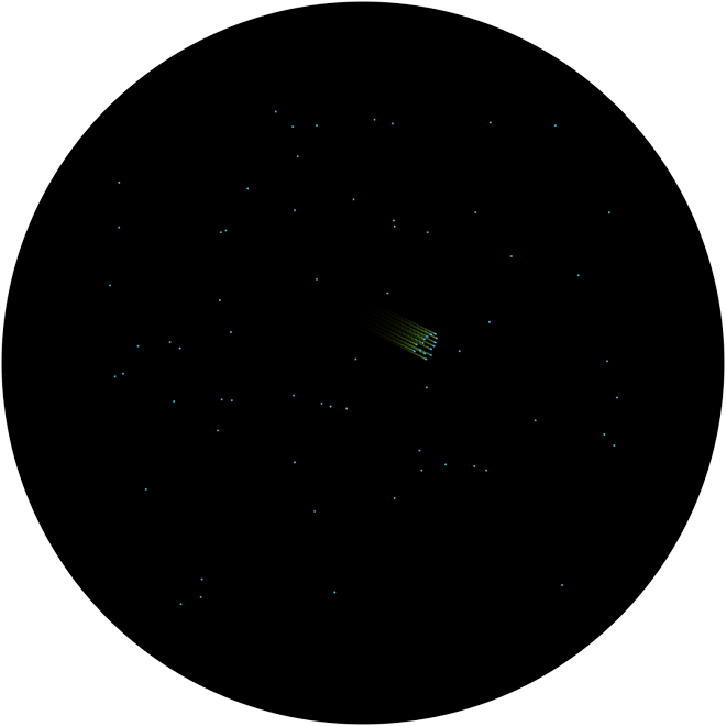
Screenshot of version 0.02. — See it live: www.masswerk.at/icss/.
Player Input
We've already addressed our plan of repurposing input methods for the PDP-1 already in place thanks to Spacewar! Let's have a closer look.
Our favorite method of input is, of course, the first gamepads to be attached to a computer ever, MIT's original "control boxes". (For the purpose of the restored PDP-1 at the CHM they have been surrogated by a more audiences-proof solution involving arcade buttons and a layout similar to "Space Duel".)
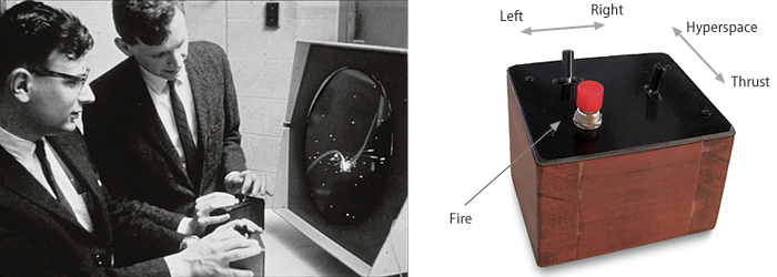
The original control boxes: Dan Edwards (left) and Peter Samson (right) playing Spacewar!, 1962 ca.,
and a modern reconstruction by Thomas A. Tilley, 2015
(Images: DEC, via the Computer History Museum (accession 102631264), Thomas A. Tilley, 2015.)
The other input method is the testword, an array of console switches to set up an 18-bit register.
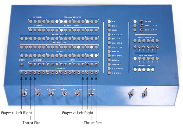
PDP-1 control pannel and usage of the testword switches for Spacewar!
(Image: Marcin Wichary, 2008, CreativeCommons; edited, N.L.)
Whatever device we're using, the signal for any of the player controls is encoded as follows:
bits:          0  1  2' 3  4  5' 6  7  8' 9 10 11'12 13 14'15 16 17
usage:         -PLAYER 1-                                -PLAYER 2-
semantics:     L  R  T  F                                L  R  T  F
For our purpose we have to take care of two issues here: a) selecting the input method of choice, and b) mixing the player inputs into a single one to be used by the game (so it doesn't make a difference which one of the two player inputs is supplied).
For chosing the input method, we go with the proven method used by Spacewar!, a double start address. The usual one at 4 will configure the game for the control boxes, an alternate one at 5 for use with the testword switches:
3/	jmp sbf				/ ignore seq. break
	jmp a0				/ start addr, use control boxes
	jmp a1				/ alt. start addr, use testword controls

/...

/here from start

a0,	law rcb				/ configure to read control boxes (sa 4)
	dap rcw
	jmp a2

a1,	law rtw				/ configure to read testword (sa 5)
	dap rcw

/start a new run

a2,	jsp bsi				/ start of main

/...

rcw,	jsp .				/ read player input

/...


/control word get routines

/read control boxes
rcb,	dap rcx
	cli
	iot 11
rcx,	jmp .

/read testword
rtw,	dap rtx
	lat
	swap
rtx,	jmp .
For the control boxes, we use instruction "iot 11", mixing the new input with the contents of IO. (Therefor we'll have to clear the IO register by "cli" before.)
For the testword controls, instruction "lat" transfers the current state of the switches into AC. We normalize this method by transferring this into IO by a swap.
The location of the chosen subroutine is put into the address part of the "jsr" to read the input, either by the path from start address 4 over label "a0", or by start address "5" and the code at label "a1". (Label "a2" marks our old start of the main routine.)
Now that we've managed the input sources, we'll have to merge the two possible player inputs. We prefer to have the result in the highest 4 bits (so that we may apply simple checks for the sign to inspect the bit in msb-position).
rcw,	jsp .				/read control word
	cla				/ clear ac
	dio \cw				/ store io in variable \cw
	rcr 4s				/ rotate lowest 4 bits of io into ac
	ior \cw				/ inclusive or \cw
	dac \cw				/ deposit merged inputs in \cw

	swap				/ put it into IO
By this we've the merged input stored in variable \cw and (after the final swap) in the IO-register. To parse the sign-bit in IO, the instruction "spi" (skip on IO positive) is exactly what we want. Let's parse and process rotations:
Rotating the Ship
	lac \rth			/load angle
	spi				/sign cleared in io?
	add raa				/no, add angular acceleration (ccw)
	ril 1s				/next bit
	spi
	sub raa				/rotate clockwise

/game parameters
raa,	2000				/ rocket angular acceleration
After normalizing our angle (0 .. 2π) we calculate the sine cosine and store them in variables "\sn" and "\cs":
	sma				/normalize 0 >= angle >= 2Pi (311040)
	sub (311040
	spa
	add (311040

	dac \rth			/update angle
	jda sin				/get sin, store it in \sn
	dac \sn
	lac \rth
	jda cos				/get cos, store it in \cs
	dac \cs
There are some new instructions: "sma" skips on minus AC (sign-bit set), "spa" is the opposite, skipping on a piositive contents of AC, and finally, instruction "jda" is a jump to subroutine that puts the contents of AC into the given address and jumps, quite like a normal jsr, to the location immediatly after this. Here, jda is used to transfer our angle (\rth) as the input to the sine and cosine routines.
This code is much like the one we find in Spacewar!. The beauty of this is that we're following a single path, regardless of the input. We may skip a single addition or subtraction, but all the time consuming processing is done in any case. (Since we do not have a clock, we would have to count instructions and spend them in a delay loop, otherwise.)
Now we've to introduce another macro, "scale". This is as simple as loading the contents of an address, shifting it right by given number of bit-positions and storing it in another address. We'll use it here mainly for its expressive qualities. As soon as we're seeing this, we know that it's about scaling a value.
define scale A,B,C
	lac A
	sar B
	dac C
	term
Also, we add a two common definitions to the head of our code:
	mul=mus
	div=dis
These are defining symbols for mnemonics that are not defined in Macro out of the box, concerning the hardware multiply/divide. Early machine came just with a special shift instruction for a partial multiplication step (mus) or division step (dis). While the hardware multiply/divide option repurposes the opcodes of the earlier, partial instructions, new mnemonics are used to mark the difference.
What's missing? Updating the spaceship.
Position and Graphics
Since our drawing routine starts at the tip of the rocket, we must get ahead of the center of our ship (as in "\rpx" and "\rpy"). To do so, we apply a scaled version of the unit vector. While we have to handle the ship position anyway, we may also update this one by adding a constant delta x and delta y in order to let the ship float accross the screen.
Finally, we compose the components for our drawing routine, also scaled versions of the unit vector. With these in place, we call the drawing routine at label "rdo": First we draw a the dot at the stern, then we draw one of the sides in a first pass, invert the lateral offset components and redo with a second pass for the other side. As we're, again, sure to spend at least 50 microseconds between any two display commands, we may go with the fire and forget varsion dpy-i.
And here is the complete code, so far:
ironic computer space  0.02  nl 2016-10-14


	mul=mus
	div=dis

define initialize A,B
	law B
	dap A
	term

define index A,B,C
	idx A
	sas B
	jmp C
	term

define swap
	rcl 9s
	rcl 9s
	term

define load A,B
	lio (B
	dio A
	term

define setup A,B
	law i B
	dac A
	term

define count A,B
	isp A
	jmp B
	term

/macros specific to the program

define scale A,B,C
	lac A
	sar B
	dac C
	term

define random
	lac ran
	rar 1s
	xor (355671
	add (355671
	dac ran
	term


3/	jmp sbf				/ ignore seq. break
	jmp a0				/ start addr, use control boxes
	jmp a1				/ alt. start addr, use testword controls


/game parameters

raa,	2000		/ rocket angular acceleration
ran,	0		/ random number


/routine to flush sequence breaks, if they occur.

sbf,	tyi
	lio 2
	lac 0
	lsm
	jmp i 1


/subroutines for background display

nos=77 	/number of stars

/table of stars coors (nos words, 9 bits x and 9 bits y)
bst,	. nos/

/setup (nos random coors starting at bst)

bsi,	dap bsx				/ deposit return address
	init bsc, bst			/ deposit first addr of bst in bsc
bsl,	random				/ get a new random number
bsc,	dac .				/ store it in current loc of st
	index bsc, (dac bst+nos, bsl	/ increment bsl, repeat at bgl for nos times
bsx,	jmp .				/ return


/display background stars (displays every 2nd frame only)

bg,	dap bgx				/ deposit return address
	isp bgc				/ increment bgc, skip on positive
bgx,	jmp .				/ return
	law i 2				/ load -2 into ac
	dac bgc				/ deposit in bgc to reset frame counter
	init bgl, bst			/ init bgl to first addr of stars table
bgl,	lac .				/ get coors of next star (x/y)
	cli				/ clear io
	scr 9s				/ shift low 9 bits in high 9 bits of io (x)
	sal 9s				/ move remaining 9 bits in ac in high part (y)
	add bgv				/ add vertical offset
	swap				/ swap contents of ac and io
	add bgh				/ add horizontal offset
	dpy-i				/ display a dot at coors in ac (x) and io (y)
	index bgl, (lac bst+nos, bgl	/ repeat the loop at bgl nos times
	jmp bgx				/ return

bgc,	0
bgh,	0
bgv,	0

/sine-cosine subroutine_ Adams associates
/calling sequence= number in AC, jda sin or jdacos.
/argument is between .+2 pi, with binary point to right of bit 3.
/answer has binary point to right of bit 0.  Time = 2.35-? ms.
/changed for auto-multiply , ddp 1/19/63

cos,	0
	dap csx
	lac (62210
	add cos
	dac sin
	jmp .+4

sin,	0
	dap csx
	lac sin
	spa
si1,	add (311040
	sub (62210
	sma
	jmp si2
	add (62210

si3,	ral 2s
	mul (242763
	dac sin
	mul sin
	dac cos
	mul (756103
	add (121312
	mul cos
	add (532511
	mul cos
	add (144417
	mul sin
	scl 3s
	dac cos
	xor sin
	sma
	jmp csx-1
	lac (377777
	lio sin
	spi
	cma
	jmp csx

	lac cos
csx,	jmp .

si2,	cma
	add (62210
	sma
	jmp si3
	add (62210
	spa
	jmp .+3
	sub (62210
	jmp si3

	sub (62210
	jmp si1


/here from start

a0,	law rcb				/configure to read control boxes (sa 4)
	dap rcw
	jmp a2

a1,	law rtw				/configure to read testword (sa 5)
	dap rcw

/start a new run

a2,	jsp bsi				/ initial setup of bg-stars
	dzm bgh				/ reset offsets of stars to zero
	dzm bgv

/rocket reset

ar,	dzm \rth			/ rotational angle
	lac (-140000
	dac \rpx			/ pos x
	cma
	dac \rpy			/ pos y
	lac (1000
	dac \rdx			/ dx
	lac (-400
	dac \rdy			/ dy

/main loop

fr0,	load \ict, -4500		/ initial instruction budget (delay)

	jsp bg				/ display background
	jsp rkt				/ rocket routine

	count \ict, .			/ use up rest of time of main loop
	jmp fr0				/ next frame


/player rocket routine

rkt,	dap rkx
rcw,	jsp .				/read control word
	cla				/merge (or) spacewar player inputs
	dio \cw				/ highest and lowest 4 bits in io
	rcr 4s				/ (rotate ccw, rotate cw, trust, fire)
	ior \cw				/ store them in high pos of \cw
	dac \cw

	swap				/parse and process rotation
	lac \rth			/load angle
	spi				/sign cleared in io?
	add raa				/no, add angular acceleration
	ril 1s				/next bit
	spi
	sub raa
	sma				/normalize 0 >= angle >= 2Pi (311040)
	sub (311040
	spa
	add (311040
	dac \rth			/update angle
	jda sin				/get sin, store it in \sn
	dac \sn
	lac \rth
	jda cos				/get cos, store it in \cs
	dac \cs

	scale \sn, 5s, \sn1		/get position of rocket tip
	scale \cs, 5s, \cn1
	lac \rpx
	add \rdx
	dac \rpx
	sub \sn1
	dac \px
	lac \rpy
	add \rdy
	dac \rpy
	add \cn1
	dac \py

	scale \sn, 6s, \sn4		/scaled sine 4 steps
	dac \sm4
	sar 1s
	dac \sn2			/scaled sine 2 steps
	dac \sm2
	sar 1s				/scaled sine single step
	dac \sn1
	dac \sm1
	scale \cs, 6s, \cn4		/same for cosine
	dac \cm4
	sar 1s
	dac \cn2
	dac \cm2
	sar 1s
	dac \cn1
	dac \cm1

	jsp rod				/display it

	lac \ict			/update instruction count
	add (1000
	dac \ict

rkx,	jmp .


/control word get routines

/read control boxes
rcb,	dap rcx
	cli
	iot 11
rcx,	jmp .

/read testword
rtw,	dap rtx
	lat
	swap
rtx,	jmp .


/rocket display
/ step rearwards -  x add \sn1, y sub \cn1
/ step outwards  -  x add \cm1, y add \sm1
/ step inwards   -  x sub \cm1, y sub \sm1

rod, 	dap rox
	stf 6			/set flag 6
	lac px
	lio py
	dpy-i

rop,	swap			/y +3, x +3
	sub \cn2
	sub \cn1
	add \sm2
	add \sm1
	swap
	add \sn2
	add \sn1
	add \cm2
	add \cm1
	dpy-i

	swap			/y +4, x +2
	sub \cn4
	add \sm2
	swap
	add \sn4
	add \cm2
	dpy-i

	swap			/y +4, x +1
	sub \cn4
	add \sm1
	swap
	add \sn4
	add \cm1
	dpy-i

	swap			/y +4, x -1
	sub \cn4
	sub \sm1
	swap
	add \sn4
	sub \cm1
	dpy-i

	swap			/y +5, x +4
	sub \cn4
	sub \cn1
	add \sm4
	swap
	add \sn4
	add \sn1
	add \cm4
	dpy-i

	swap			/y +2, x-6
	sub \cn2
	sub \sm4
	sub \sm2
	swap
	add \sn2
	sub \cm4
	sub \cm2
	dpy-i

	swap			/y +4, x+4
	sub \cn4
	add \sm4
	swap
	add \sn4
	add \cm4
	dpy-i

	szf i 6			/flag 6 set? (skip on not zero)
rox,	jmp .			/no, return
	clf 6			/clear flag 6
	lac \cm1		/invert unit vector components
	cma
	dac \cm1
	lac \sm1
	cma
	dac \sm1
	lac \cm2
	cma
	dac \cm2
	lac \sm2
	cma
	dac \sm2
	lac \cm4
	cma
	dac \cm4
	lac \sm4
	cma
	dac \sm4
	lac px			/load first pos
	lio py
	jmp rop			/second pass for other side


	constants
	variables

	start 4
Note: The amount used to update the instruction count is completely arbitrary.
And in case, we didn't have this before: Instruction "cma" complements the value in the accumulator.
Thanks to the gods of wires and transistors, almost everything worked out of the box. That's especially nice, because I stripped any debugging from the emulator long ago, since it was original meant to run authentic, historical programs.
That is, with one exception: The spaceship was rotating constantly. I stared at the input instructions, I stared at the code for parsing the inputs — nothing of notice here, and still… Let's comment something out, — and still…
Finally, I found, I had used a "dac" for a "dap" where the address of the control word get routine of choice is inserted into the instruction at label "rcw", thus rather owerwriting the whole instruction word instead of fixing up the address part only. — The dangers and perils of self-modifying program code!
Anyway, see the code live in action: ▶ www.masswerk.at/icss/.
*****
P.S.: An Interesting Find
While tinkering around, I remebered that an early version of Spacewar! (2B) was using a slighly different constant to modify the random seed, namely 355671 instead of the constant 355670, we're finding in later versions. And using this one, we get a much nicer starfield, even reminding of some constellations! I've always been wondering, why the random number was changed at all. Coincidentially, Spacewar! started with a random starfield, too, before Peter Samson added his realisticly moving starfield, the Expensive Planetarium. Maybe, the earlier version of the constant was specially crafted for the purpose of the starfield, while exposing properties that where not that ideal for features that became more important later on, like the particle effect of the explosions.
That's all for this post.
▶ Next: Episode 4: “A Rocket Ship That You Control”
◀ Previous: Episode 2: Stars & Sync
▲ Back to the index.
2016-10-15, Vienna, Austria
www.masswerk.at – contact me.
— This series is part of Retrochallenge 2016/10. —