Inside Spacewar!
Part 1: The "Expensive Planetarium"
(Introduction · The Code · The Stars of the Heavens · Instructing the PDP-1 · The Macro Assembler · The Main Routine · The Grand Finale Being the Preludium: Spacewar! 2b)
This is the first part of a loose series of articles on software archeology, attempting to explain the code of Spacewar!, the earliest known digital video game. In the first of these articles we're going to explore an isolated part of Spacewar!, Peter Samson's "Expensive Planetarium", the famous program in the program, responsible for the display of the background starfield.
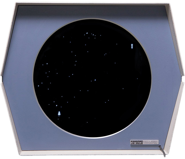
The Expensive Planetarium in Spacewar! (Montage)
Credits: Screen-shot by J.M. Graetz 1962; Type 30 CRT by CHM / Mark Richards 2013; Montage: Norbert Landsteiner 2014
Investigating the source code of Spacewar! may provide some insight, what programming actually was like, half a century ago, before the advent of programming languages, before there was an OS or a ROM, when programs were jockying the bare machine. And it provides the thrills of peeking over the shoulders of the demi-gods, of spanning time to watch the olympians at work. For this, the concept of source code as a text may be of help, meaning that even a functional prose, like a program, is still a text production including all the underlying implications, and that at least some of these would be still available in the traits of the resulting text. We may return to this from time to time.
For its isolated nature, Peter Samson's "Expensive Planetarium" provides a perfect starting point for this endeavor. Inserted into the main program right in the "hot" phase of its development in March 1962, the "Expensive Planetarium" provides an atmospheric backdrop by its slowly, but steadily moving starfield and, on the functional side, a reference point for the maneuvering starships, navigated by the virtual astronauts in front of the scope. Moreover, by its realism, it adds much to the claim of Spacewar! of providing a realistic simulation of Newton's laws and spaceflight.
BTW: ▶ You can play here the original code of Spacewar! running in an emulation.
As we are going to have a look at the code, it might be appropriate to include the standard credits first, which are also providing some historical data:
Spacewar! was conceived in 1961 by Martin Graetz, Stephen Russell, and Wayne Wiitanen. It was first realized on the PDP-1 in 1962 by Stephen Russell, Peter Samson, Dan Edwards, and Martin Graetz, together with Alan Kotok, Steve Piner, and Robert A Saunders. Spacewar! is in the public domain, but this credit paragraph must accompany all distributed versions of the program.
The Code
The source code of the "Expensive Planetarium", for the PDP-1 Macro assembler, looks like this:
/background display ·  3/13/62, prs.

	define
dislis J, Q, B
	repeat 6, B=B+B
	clf 5
	lac flo+R
	dap fpo+R
fs,	dap fin+R
	dap fyn+R
	idx fyn+R

fin,	lac	/lac X
	sub fpr	/right margin
	sma
	jmp fgr+R
	add (2000
frr,	spq
fou,	jmp fuu+R
fie,	sub (1000
	sal 8s
fyn,	lio	/lio Y
	dpy-i+B
	stf 5
fid,	idx fyn+R
	sad (lio Q+2
	jmp flp+R
	sad fpo+R
	jmp fx+R
	dap fin+R
	idx fyn+R
	jmp fin+R

fgr,	add (-20000+2000
	jmp frr+R

fuu,	szf 5
fx,	jmp flo+R+1	/return
	idx flo+R
	idx flo+R
	sas (Q+2
	jmp fid+R
	law J
	dac flo+R
	jmp fid+R

flp,	lac (lio J
	sad fpo+R
	jmp fx+R
	dap fin+R
	law J+1
	dap fyn+R
	jmp fin+R

fpo,	lio
flo,	J
	terminate


	define
background
	jsp bck
	termin

bck,	dap bcx
	szs 40
	jmp bcx
	isp bcc
bcx,	jmp .
	law i 2
	dac bcc
	dislis 1j,1q,3
	dislis 2j,2q,2
	dislis 3j,3q,1
	dislis 4j,4q,0
	isp bkc
	jmp bcx
	law i 20
	dac bkc
	law i 1
	add fpr
	spa
	add (20000
	dac fpr
	jmp bcx

bcc,	0
bkc,	0
fpr,	10000
And this is the assembler code generating the data, often mistaken for the code itself (various data points of a few pages length are omitted in favor of a more comprehensive listing):
stars by prs  for s/w 2b

6077/

/stars 1 ·  3/13/62, prs.

	decimal

	define
	mark X, Y
	repeat 8, Y=Y+Y
	8192-X	Y
	terminate

1j,	mark 1537, 371	/87 Taur, Aldebaran
	mark 1762, -189	/19 Orio, Rigel
	mark 1990, 168	/58 Orio, Betelgeuze
	mark 2280, -377	/9 CMaj, Sirius
	mark 2583, 125	/10 CMin, Procyon
	mark 3431, 283	/32 Leon, Regulus
	mark 4551, -242	/67 Virg, Spica
	mark 4842, 448	/16 Boot, Arcturus
1q,	mark 6747, 196	/53 Aqil, Altair

2j,	mark 1819, 143	/24 Orio, Bellatrix
	mark 1884, -29	/46 Orio
	mark 1910, -46	/50 Orio
	mark 1951, -221	/53 Orio
	mark 2152, -407	/ 2 CMaj
	mark 2230, 375	/24 Gemi
	mark 3201, -187	/30 Hyda, Alphard
	mark 4005, 344	/94 Leon, Denebola
2q,	mark 5975, 288	/55 Ophi

3j,	mark   46, 333	/88 Pegs, Algenib
	mark  362, -244	/31 Ceti
	mark  490, 338	/99 Pisc
	...

3q,	mark 7849, 334	/54 Pegs, Markab

4j,	mark    1, -143	/33 Pisc
	mark   54, 447	/89 Pegs
	mark   54, -443	/ 7 Ceti
	...

4q,	mark 8188, -407	/ 2 Ceti

	start 4
The Stars of the Heavens
Let's have a look at the data part first. One of the reasons for this being often mistaken for the program itself, is because the star-map came in a separate listing or paper tape, to be fed into the reader after the main program.
Excursus — The Code Organisation of Spacewar!
Spacewar! was organised in a modular way, with a main part including the code for the main loop of the game, and some other parts covering the code that would remain unchanged in major versions, stored on separate tapes. So, if you would want to play with the code, you had actually to fiddle width a single one of these tapes only. These parts were
- A definition of some macros commonly used at MIT, not included in any of the Spacewar! listings.
- Spacewar – part 1: This included the table of game constants, some macro definitions special to Spacewar! (e.g., the random number generator, or macros for initializing a table of values), basic sub-routines for multiplications and divisions, the sine-cosinus routine that started the actual coding ("All right, Russell, here's a sine-cosine routine; now what's your excuse?"), an integer square root routine, Dan Edwards' outline compiler for drawing spaceships, the code generating the display of the central gravitational star, and, finally, the main part of the "Expensive Planetarium". — We could call this the library part of Spacewar!.
- Spacewar – part 2: The main part of the game, handling the actual logic.
- The data of the star-map.
*****
The star-map, the last and final part of Spacewar!, starts with the title, signed by Peter Samson ("prs") and indicating the first version of Spacewar! that would actually include the Expensive Planetarium (Spacewar! 2b).
(This was more than a comment, the title would have also been printed at the top of each page of the assembler output.)
So, what data is this? Obviously it is giving some coordinates of stars, grouped in sections labeled 1j .. 4j and 1q .. 4q. (Any symbol at the beginning of a line that is followed by a comma is a label for the very memory register, the next instruction would be located.) There are some rumors that this would have been a map of the night sky as seen from the roof of MIT — and, in deed, this would have been perfectly possible: MIT was actually NASA's first contractor for the Apollo project (with a contract dating from 1961) for the development of navigation systems, including a system based on gyroscopes and an optical sextant system. For this there had been test facilities at the roof of MIT, and persumingly some data would have been available at that time. But we know better from J. M. Graetz's article "The Origin of Spacewar" (Creative Computing, August 1981) and from his paper for the first DECUS conference, "Spacewar! Real-Time Capability of the PDP-1" (DECUS Proceedings 1962: Papers and Presentations of the Digital Equipment Computer Users Society, Maynard, Massachusetts, 1962, 37-39):
Using data from the American Ephemeris and Nautical Almanac, Samson encoded the entire night sky (down to just above fifth magnitude) between 22½ degrees N and 22½ degrees S, thus including most of the familiar constellations. (The Origin of Spacewar)
However, Peter Samson of M.I.T. has written a program which displays a star map of the sky as seen from the Earth's equator. The size of the scope limits the extent of the map to a 45° segment of the heavens. Stars down to just above fifth magnitude are displayed. The display moves imperceptibly across the face of the scope from left to right, and, given time, the complete band of stars of this section of the map will be displayed. (DECUS Proceedings 1962)
So we know, it's data from the American Ephemeris and Nautical Almanac — but how is it encoded? Having a closer look at the data, we'll discover that these are sets of x/y values in the range of (decimal) 0 .. 8192 along the x-axis and (decimal) mark (more on this a bit later) gives us the order of its arguments, first X, followed by Y. The individual insertions of the macro mark are followed by comments (everything in a line following a slash is a comment) pointing out the individual stars. Moreover, we may conclude that that the labels (1j .. 4j, 1q .. 4q) are grouping the stars by magnitute (the apparent brightness), from the first up to including the fourth magnitude. We may also observe that the data is ordered inside these groups by ascending values of the x-coordinate (1537, 1762, ..., 6747). Finally, we may infer that a label "nj" is persumingly marking the start address of a group and that a label "nq" is marking the last set of coordinates in a group.
In order to understand these coordinates, we have to mind the display facilities of the DEC PDP-1, the computer meant to run this code. The DEC Type 30 CRT display was a point plotting display featuring a technical resolution of 1024 random accessible plotting locations both along the x and the y axes. The origin of the display's coordinate system was in the center of the display, stretching from -512 to +512 in both directions. (This was actually the default mode, there were also 3 other possible positions of the origin to be selected by each individual display instruction, but Spacewar! was always using the default option.)
Based on this information we may understand the specific scaling of the data: The y-domain is scaled to the dimensions of the display with the scaling of the x-domain following roughly from this in proportion.
Now, let's have another look at the details of the code wich is producing the data table of the star-map:
The first line following the title specifies the starting position of the code by setting the program counter. Any expression followed immediately by a slash is setting the program counter to the position provided by the expression. In this case to octal 6077, which is quite at the end of the PDP-1's 12-bit address space, ranging from 0 to 77777.
The next line is a comment, providing historians with the exact date of the code (13 March 1962).
The pseudo instruction decimal is instructing the assembler to treat all the following values as decimal values, as opposed to octal values which would have been the default mode.
Following to this, there is the definition of the macro mark, bracketed inside the assembler keywords (pseudo instructions) define and terminate:
	define
	mark X, Y
	repeat 8, Y=Y+Y
	8192-X	Y
	terminate
The line "mark X, Y" provides the name of the macro and the names of the arguments, the macro would be accepting. (Macro parameters are all upper case, as opposed to all other symbols being strictly lower case.) The pseudo instruction "repeat 8," instructs the assembler to repeat (internally) the instructions given in the rest of the line 8 times. This is adding the value of parameter Y eight times to itself, which corresponds to a multiplications by 2^8 or to performing 8 bit-wise shifts to the left. The final line inserts the result of 8129 minus the actual value of X, followed by the the value of Y resulting from the previous operation. (The value of decimal 8192 may appear to be a bit deliberate, but it makes perfectly sense, when given in the octal representation of 20000.)
So, with the program counter set to 6077, the macro code
1j, mark 1537, 371 /87 Taur, Aldebaran
results in the insertion of the following code (all numbers octal)
	loc.   contents
	06077  014777
	06100  271400
and the label "1j" pointing to the address 6077.
What was this macro good for? Let's have a closer look at the dpy instruction adressing the display: This instruction did not include the coordinates (but some other options like the brightness of the blip to be displayed, as we'll see soon), instead the coordinates were expected in the two user-addressible registers of the PDP-1, the accumulator (AC) and the i/o-register (IO), providing the x-location and the y-location respectively. Moreover, these coordinates were expected in bits 0-9 (of a total word length of 18 bits, with bits counted from the highest significant bit in the left-most position). For this, the value would have to be shifted by 8 bits to the left, which is exactly what the repeat statement does. (The Macro assembler only supported basic arithmetics, thus the shift had to be accomplished by repeating an addition 8 times.) Thanks to this, the y-information is now readily prepared to be deployed in the IO register. The value of 8129, the x-information is subtracted from, corresponds to the maximum value of the x-domain. (We'll see later, what this horizontal flip would have been good for, and, finally, by what kind of information the stars were actually ordered.)
The final pseudo instruction "start 4" is actually ending the source code, instructing the assembler to output any Read-In-Memory (RIM) tapes with an initial jump to the start address of 4 (which was also the default start address for any PDP-1 program). With the data thus prepared, we may approach the code that is actually managing the display.

The star-map of the Expensive Planetarium.
(rendered at 4096 x 512 px, viewport 645 x 512 px, ↔︎ horizontally scrollable)
Instructing the PDP-1
Before we dive into some operational code, it might seem appropriate to spend a few lines on the machine in order to understand its language. The PDP-1 — or, by its full name, the Digtal Equipment Corporation's Programmed Data Processor-1 — was an 18-bit solid state machine with its CPU running at a cycle speed of 5 microseconds. An instruction acting only on the CPU and its registers (the accumulator and the i/o register, which would also double as an extension of the accumulator to form a single rgister of 36 bits length with a few instructions) would be processed in a single cycle, instructions involving memory access would use another cycle, and any indirect ("deferred") memory accesses would add another one. This was good for 100,000 additions per second, including memory access — a quite remarkable speed providing the means for real-time processing.
As usual in computing before IBM's system/360, bits came in groups (or nibbles) of three, with the PDP-1 being no exception. For this octal notation came handy, since all three bits of a nibble set to high would give the binary numerical representation of 7. We will stick to this and any numerical notation will furtherly refer to an octal value, if not explicitely stated otherwise.
The 18-bit instructions of the PDP-1 were storing both instructions and addresses in a single word, with the highest 5 bits providing the op-code, and the lower 12 bits providing the address of a memory location (commonly referred to as Y). The 12 bits work out to a maximum address space of 7777 (or decimal 4096) memory locations — which was also the PDP-1's default memory setup. (By adding a special module up to 12 of these memory modules could be added which would be addressed either by bank switching or by a special 16-bit extended addressing mode. But as for Spacewar!, we'll stick with the 4096 x 18-bit default setup.)
                      1 1 1 1 1 1 1 1
  0 1 2 3 4 5 6 7 8 9 0 1 2 3 4 5 6 7
┌──────┴───┬─┼─────┴─────┴─────┴─────┐
│  opcode  │i│   address / operand   │     PDP-1 instruction format
└──────────┴─┴───────────────────────┘
The 5th bit, the "i"-bit or defer bit, would modify most instructions, when set. With instructions involving a memory access this would alter the instruction to not only looking up the address given in the address part, but would cause the computer to use the lower 12 bits of the contents of this location for another lookup, in potentially infinite recursion. With other instructions, the presence of the i-bit would modify the semantics of the instruction, e.g., invert the condition of a conditional skip. (Conditional skips were the only means of branching — there were no conditional jumps, but this made some sense with the instruction set of the PDP-1.)
When the contents of a register or a memory location was treated as a numeric value, the full 18 bits would be used to represent a value, with the sign bit in the most significant position (bit 0). Negative values were represented in one's complement (a simple flip of all bits).
Transfer instructions came in some flavors and would either deposit the full contents of a register into the given location, or would only affect the bits representing the op-code (the instruction part), or the part representing the address of a location (the address part). This did not only provide a remarkable flexibility, but was also resulting in notoriously self-modifying programs, which was also the dominant programming paradigm of the time. — In fact, we would only seldomly encounter a data structure such "well behaved", as we've found it in the star-map of the "Expensive Planetarium". Rather, data and processing instructions would have been commonly intermangled. Moreover, the code would also be modified in the course of running the process, as would be especially the case with the address part of jump instructions. (Notably, in the absence of a dedicated processor stack, return addresses had to be fixed up at runtime.)
While this might seem quite intimitating to a modern programmer, this was surprisingly straight-forward and comfortable to hack, quite like MIT's handcrafted assembler.
The Macro Assembler
Equally straight forward is the Macro assembler (originally developed for the TX-0 and ported to the PDP-1 in a two days effort). Any smbols, including those designating instructions and some special constants, are simply added up: The sum of all symbols in a line makes the instruction code for the given memory location. Symbols may be defined anywere, but only once. Macros may be called in any place, in order to insert the code produced by them in place. Macro names and pseudo-instructions (assembler directives and keywards) would be at least 4 characters long and could be abbreviated to at least 4 characters. Moreover, the assembler assists by the handling of variables, which were marked up by an upper stroke in any of the characters of their name. The assembler would reserve some space for them and would insert the according addresses to these in the final code production. (We are not dealing with any variables in this part of the code, while Spacewar! makes generally heavy use of them.) Equally, any expression starting with an opening bracket (the closing part could be omitted) would instruct the assembler to create a constant from this, to be placed in a look-up table. The address of the location in the constants table would then be used as the actual operand. (In case this expression had been used before, the reference would have been reused. And, to be exact: Constants and variables would be inserted in place of the respective keywords, usually located at the end of the program.) Any location could be assigned a label by placing a symbol in front of it, followed by a comma. — As a rule of thumb, we may keep in mind: Anything up to three characters long is a normal symbol, like an op-code or a label. Anything of 4 characters length or longer is a pseudo-instruction, like a macro or a directive.
There were some special symbols, notably "i" representing the value of the defer bit (10000), and the symbols 1s, 2s, .. 9s, representing operands for shift and rotate instructions. (Shifts and rotates shared a single op-code, with the higher 3 bits of the address part encoding the actual operation. The number of high bits in the remaining 9 lower bits of the address part would give the number of bits to shift or to rotate by. "s1" would refer to a value of 1 with a single high bit, "2s" to 2 with two bits set to high, and so on, with "s9" denoting 777 or 9 high bits, the maximum amount.)
To illustrate the workings of the Macro assembler, here is a simple example:
foo,	sar 3s          / shift the contents of AC right by 3 bits
	lac i foo+4     / load the contents of the address in foo+4 into AC
Assuming that "foo" would be a label at location 2000,
this would produce the following code:
	02000  675007   / sar: 675000, 3s: 7; 675000 + 7 => 675007
	02001  212004   / lac: 200000, i: 10000, foo: 2000; lac + i + foo + 4 => 212004
Further, there were two special symbols refering to the program counter: A dot (".") would denote the current location, an upper case "R" would denote the insertion point of the code produced by a macro definition. (Labels defined inside a macro were local to them and "R" had to be added to them in order to give the actual address, when refering to a local label. It is also for this that it's quite easy to tell, whether a specific label would be local to the macro or if it would be a global one.)
As mentioned before, a slash would start a comment, with the notable exception of a slash following immediately to an expression, in which case the program counter (the current location) would be set to the given expression.
Provided with this, we now may happily dive into some actual code.
The Main Routine
The code for displaying the "Expensive Planetarium" starts like this
/background display · 3/13/62, prs.
and — after a lengthy macro definition (dislis) — ends like this
background
	jsp bck
	termin

bck,	dap bcx
	szs 40
	jmp bcx
	isp bcc
bcx,	jmp .
	law i 2
	dac bcc
	dislis 1j,1q,3
	dislis 2j,2q,2
	dislis 3j,3q,1
	dislis 4j,4q,0
	isp bkc
	jmp bcx
	law i 20
	dac bkc
	law i 1
	add fpr
	spa
	add (20000
	dac fpr
	jmp bcx

bcc,	0
bkc,	0
fpr,	10000
From the first line we learn about the date and the author (Peter Samson, 13 March 1962), once again. Actually, this is the code variant from Spacewar! 3.1, wich differs a bit from the original version for Spacewar! 2b, but is identically used in most versions of Spacewar!. Obviously, it wasn't popular to update comments even then.
The second part is a bit more interesting. The macro definition "background" is quite mondane, including just a jump to subroutine instruction to label bck, but it provides us with the information that bck would be the main entrance point and that it would be expected to be called as a subroutine. jsp is quite like an ordinary jump instruction, with the current state of the program counter (PC) being stored inside the accumulator (AC) to be used as the return address.
The code starting at label bck is the main routine of the whole "Expensive Planetarium" (EP). Let's see, what it does.
Controlling Time
bck,	dap bcx
	szs 40
	jmp bcx
	isp bcc
The first instruction dap (deposit AC in address part) deposits the contents of the accumulator, holding currently the return address, in the address part of the location labeled bcx. This location is initially containing a "jmp . " instruction, meaning a jump to itself. (This was a convention, indicating that the actual address would be inserted at runtime.) dap will now insert the contents of AC (the return address) in the address part (lower 12 bits) of this instruction, leaving the op-code jmp as is. When the instruction at bcx will be executed, this will cause a jump to the return address.
The next instruction "szs 40" (skip on sense switch zero) is a conditional skip, skipping the next instruction, if the sense switch number 4 is not set to the high-position. (Sense switches were an array of control switches on the PDP-1's console, the number of the switch is given in the second lowest nibble, hence the operand is 40 and and not 4.) The instruction following immediately to this, is a jump to bcx (the jump to the return address) resulting in an early abortion of this code. So, sense switch 4 set will inhibit the execution of the EP's main loop and there won't be any stars displayed at all.
The next instruction is supposingly doing all the rest, since it is followed directly by the jump to the return address. Let's have a closer look.
The instruction isp (index and skip on positive) increments the contents of the location specified in the address part (bcc) by 1 and skips the next instruction, if the contents of the given location would result in a positive number (with the sign-flag in bit 0 not set). For this, we could expect the contents of the location labeled bcc to be a negative value being counted up. As long as the value is negative, the jump to the return address is executed and there will be no stars displayed. Obviously, there are calls, where the EP wouldn't display anything. Hmm...
bcx,	jmp .
	law i 2
	dac bcc
	dislis 1j,1q,3
	dislis 2j,2q,2
	dislis 3j,3q,1
	dislis 4j,4q,0
	isp bkc
	jmp bcx
	law i 20
	dac bkc
	law i 1
	add fpr
	spa
	add (20000
	dac fpr
	jmp bcx
The instruction following after the jump to the return address is executed only, if the contents of bcc would be positive (in this case zero) and the condition of the isp above was matched. In this case, the instruction "law i 2" (load AC with number) is loading the value -2 into the accumulator. (The presence of the i-bit is instructing the CPU to treat the operand as a negative number, making this the instruction "load AC with number -N".)
The next instruction "dac bcc" (deposit AC) stores the contents of the accumulator in the memory location labeled bcc. So, bcc will start at zero and will thus be set to -2. In the next run bcc will be indexed and will then be -1, resulting in a jump to the return address. In the following run bcc will be incremented again to contain the value zero, resulting in a skip and bcc will be reset to -2 again. The EP will do anything in even cycles only, returning early from the odd ones.
The next 4 pseudo instructions result in the inclusion of the macro dislis, each with parameters giving the start and end location of the stars of a specific magnitude, and a third parameter, ranging from 3 for the first call, down to 0 in the forth and last one. Obviously dislis is doing the heavy work — we'll see later.
The instruction "isp bkc" is incrementing another counter and will skip the next instruction, if the contents of the location labeled bkc would be positive (or zero). Following the pattern, we already encountered earlier, the next instruction will jump to bcx, the jump to the return address. Thus, the following instructions will be executed only, if bkc would be zero or positive: "law i 20" and "dac bkc" are loading the number -20 into the accumulator and deposit it in location bkc. — The contents of bkc will advance from -20 to 0 and will then be reset to -20 again.
The next instruction, "law i 1" loads the value -1 into the accumulator and "add fpr" will add the contents of the location labeled fpr to this, leaving the result in the accumulator. "spa" (skip on positive AC) is a conditional skip of the next instruction, if the result of the previous operation would be zero or positive. In case it would be negative, the next instruction, "add (20000" adds the constant value 20000 to this. "dac fpr" deposits the contents of the accumulator finally back into location fpr. So, on every 20th (decimal 16th) operational cycle, fpr will be incremented by one, and fpr will be in the range of 0 .. 20000. Incidentially, we already know this value: the extent of the star-map data along the x-axis. We might infer that fpr is controlling the positions of the stars advancing over time. The only task of counter bkc is to control the timing of this advancement.
The final, unconditional jump to bcx ends the code of the control loop, followed by the locations used for the three counters. We may note that fpr is initially set to 10000, pointing to the very center of the star-map.
bcc,	0
bkc,	0
fpr,	10000
In summary, the EP will be only executed, if sense switch 4 is not set. It will do any display work only every second cycle, as controlled by the counter in bcc. The position of the night sky in fpr is advanced in every (decimal) 16th display cycle (controlled by counter bkc) and will be in the range from 0 to 20000, initially starting at 10000.
A Magnitude of Stars
The macro dislis is displaying the stars of a magnitude. This is quite a lengthy macro, in fact, it is the longest one in the entire code of Spacewar! While the EP may appear to be quite short as a listing (just a single page), most of it will be inserted 4 times into the PDP-1's memory, at each of the four calls to dislis.
	define
dislis J, Q, B
	repeat 6, B=B+B
	clf 5
	lac flo+R
	dap fpo+R
fs,	dap fin+R
	dap fyn+R
	idx fyn+R

fin,	lac	/lac X
	sub fpr	/right margin
	sma
	jmp fgr+R
	add (2000
frr,	spq
fou,	jmp fuu+R
fie,	sub (1000
	sal 8s
fyn,	lio	/lio Y
	dpy-i+B
	stf 5
fid,	idx fyn+R
	sad (lio Q+2
	jmp flp+R
	sad fpo+R
	jmp fx+R
	dap fin+R
	idx fyn+R
	jmp fin+R

fgr,	add (-20000+2000
	jmp frr+R

fuu,	szf 5
fx,	jmp flo+R+1	/return
	idx flo+R
	idx flo+R
	sas (Q+2
	jmp fid+R
	law J
	dac flo+R
	jmp fid+R

flp,	lac (lio J
	sad fpo+R
	jmp fx+R
	dap fin+R
	law J+1
	dap fyn+R
	jmp fin+R

fpo,	lio
flo,	J
	terminate
From the definition, we are learning that dislis will take three parameters, J and Q, referring to the start and end point of the data of the stars of a magnitude, and a third paramtere B. Following the pattern, we already encountered in the macro mark, the repeat pseudo-instruction is apparently preparing this third parameter for later use, by shifting its contents 6 bits to the left.
Scanning the code for any ocurrencies of B, there is only a single one: "dpy-i+B". dpy is the instruction that is actually commanding the display to produce a dot on its screen. It is a subtype of the iot (i/o transfer) instruction, controlling any communications with peripheral devices. The lower two nibbles are addressing a specific device (in this case 07 for the CRT), while bits 6 to 11 would set parameters for the device. The presence of the i-bit would causes the CPU to wait for a completion pulse to be sent by the device, in order to indicate that it would have finished its operations. dpy was encoded in the Macro assembler by the inclusion of the i-bit, hence the subtraction of i in order to not have to wait for the display to return the completion pulse. Bits 9 to 11 (bit 11 being in 7th position from the right) would set the intensity of the dot to be displayed to any of the 8 brightnesses available, with 3 being the brightes, 0 the default intensity, and 4 the lowest. So, B shifted 6 bits to the left would set the brightness for these stars, and the 4 distinctive calls to disliss would assign one of the 4 most intense brightnesses to any of the 4 magnitudes of the stars to be displayed. This would be dimmed by the main loop, actually advancing to the part including these inclusions of disliss on every second run only, while the stars would still be visible in the skip-cycles thanks to the dimm afterglow of the Type 30 CRT's P7 phosphor.
So we actually know, how the stars will be displayed, so what is the rest of this macro doing?
	clf 5
	lac flo+R
	dap fpo+R
fs,	dap fin+R
	dap fyn+R
	idx fyn+R
"clf 5" (clear program flag) resets the program flag 5 to zero. (Program flags were another register of the PDP-1, providing a vector of flag-bits that could be set or reset and skipped on. Also, some devices would set a program flag, e.g., to indicate that there was an input waiting to be processed.)
"lac flo+R" loads the contents of location flo into the accumulator and the three following daps are depositing this value in the address parts of locations fpo, fin, and fyn, which is then incremented by the instruction "idx fyn+R" (index value in address at Y and leave the incremented value of Y in AC).
(The R, added to all these addresses, is representing the insertion point of the macro, to be added to the relative addresses of the local labels in the final production of this macro.)
The value in location flo is preset with parameter J, the address of the first x-coordinate of the specifice range of stars, which is thus copied to three other addresses. The final increment of the address copied to fyn makes this effectively a pointer to the first y-coordinate, following immediately in memory.
With everything set up nicely, we're ready for some real work starting at the label fin:
fin,	lac	/lac X
	sub fpr	/right margin
	sma
	jmp fgr+R
	add (2000
frr,	spq
fou,	jmp fuu+R
fie,	sub (1000
	sal 8s
fyn,	lio	/lio Y
	dpy-i+B
	stf 5
"lac" loads the contents of the address that was inserted here before (by the first of the dacs above) into the accumulator and we are confirmed by the comment that this would be the x-value. The next "sub fpr" subtracts the value in location fpr from this. As we're told by the comment, fpr is the current position of the right margin, and this is also the counter we've already seen in the part of the code discussed earlier (containing a value between 0 and 20000, which also serves the explanation for the preparatory subtraction in the macro mark).
"sma" (skip on minus AC) skips the next instruction, if the result of this subtraction — now the new contents of AC — would be negative. A positive value would indicate that the position would be off-screen to the right, beyond the right margin, and a jump to the local label fgr will be executed.
If we're still in bounds at the right side, "add (2000" adds the constant 2000 to this (octal 2000 being decimal 1024 or the width of the display). — Now we may also understand the condition checked by sma above: Since the display's width is 2000 and we were adding 2000 to the x-value here, any initial value equal to or greater than zero would be out of bounds to the right of the display's coordinates system.
At frr, the instruction "spq" skips, if the contents of the accumulator would be positive, but not zero. (spq is actually not an official op-code of the PDP-1, but the skip instructions were micro-coded and could be combined into unions to form new instructions, which was actually encouraged by the manual. spq equaled the value of "sza i sma-szf" or the instruction word 650500.) Anyway, this is the check for the left border: If the x-value would be still negative after the addition, we would be off-screen to the left side and the next instruction, labeled fou, would take us to location fuu by executing "jmp fuu+R".
If still in bounds, the code at fie prepares the value in the accumulator to serve the purpose of providing the X-coordinate for the dpy instruction, by adding the constant 1000 and by shifting the result 8 bits to the left by executing "sal 8s" (shift AC left). (We may recall that the display's coordinate system was stretching from decimal -512 to +512, with the origin at the center of the screen, and that the X-coordinate would be expected in the accumulator in bits 0-9.)
The instruction labeled fyn loads the Y-coordinate into the IO register (lio: load into IO), from the address previously deposited there in the setup-steps. Since this value was already prepared by the macro mark, no prepatory work is needed for this one. "dpy-i+B" finally brings this to the display, enlightening us with the delights of a night sky in the exact brightness as specified in parameter B.
The final "stf 5" (set program flag) sets the program flag 5, which has been reset to zero at the start of the macro. (We could guess that this would be some kind of "busy" flag, indicating that any display work was actually done.)
Now we have successfully put a star on the scope and we're left with the task of advancing on the coordinates table and checking the bounds of J and Q. Let's see, how this was done.
Looping Over the Table
fid,	idx fyn+R
	sad (lio Q+2
	jmp flp+R
	sad fpo+R
	jmp fx+R
	dap fin+R
	idx fyn+R
	jmp fin+R
As we arrive at label fid, it's time to advance the pointers. "idx fyn+R" increments fyn to point to the x-coordinate of the next star and leaves the result of the increment in the accumulator. This is then compared by "sad (lio Q+2" (skip on AC not equal Y) to a constant assembled of the values of lio and Q+2, representing an instruction to load the first address location outside our range of stars. If equal, we're out of bounds and jump to the label flp with the next instruction.
If still in business, "sad fpo+R" is another comparison, this time to the value in fpo (the copy of the initial x-value). If the values are equal, we miss the skip and make a jump to label fx (to execute a jump to the return address) in the next instruction. (We'll see later, when investigating the code at flp, that the values in AC and fpo would be equal, because we did a full wrap around the range of stars. Since we thus arrived at an address already handled, we're done and may exit gracefully.)
If not equal, the "jmp fx" is skipped and, with all edge-cases handled, the address-pointers are finally updated: "dap fin+R" stores the new x-value in the address part of fin, and another index on fyn ("idx fyn+R") advances the address to point to the next y-coordinate. By this, we're ready for another iteration, initiated by "jmp fin+R".
These leaves us with handling the various break conditions of this loop.
fgr,	add (-20000+2000
	jmp frr+R
The first one, labeled fgr, would be reached, if the x-position of the current star would be out of bounds beyond the right margin (bearing a positive value even after the subtraction of 20000). The instruction "add (-20000+2000" subtracts the total extend of the x-domain from the x-value (currently in AC) and adds the width of the display (2000) to this. By this, the code is performing a full wrap around on the position in the accumulator and also recenters it for the display. This is handling the edge case (pun intended), when crossing the very bounds of the x-domain.
The following jump to frr (a part of the code, we've already seen), checks by spq, if this would be inbounds on the left side (affirming that this would be an edge case), and the star would be displayed. If not, the instruction at fou would take us to label fuu.
fuu,	szf 5
fx,	jmp flo+R+1	/return
	idx flo+R
	idx flo+R
	sas (Q+2
	jmp fid+R
	law J
	dac flo+R
	jmp fid+R
Label fuu is reached, if the current x-value would be off-screen to the left. "szf 5" (skip on program flag) will skip, if our "busy flag" would still be zero and we didn't display a star yet. In case we would have already displayed some (like, when comming here by passing fgr), we're done (since our data is nicely ordered) and the next instruction, labeled fx, provides the final jump to the return address by "jmp flo+R+1". (Since flo is the label of the last word produced by this macro, a jump to the address immediately following to this will set the program counter to the next instruction outside the macro.)
If flag 5 would still be zero, we haven't displayed any yet and the following two instructions, both "idx flo+R", would increment the pointer in flo (the one initially starting with the first x-value provided by J) twice to point to the next pair of coordinates.
"sas (Q+2" (skip on AC equal Y) checks, if we overshot and would be out of range. If not, we would proceed with the next star by jumping to fid. If we overshot, "law J" would load the value of parameter J (the very first x-value) into the accumulator and "dac flo+R" would deposit this in the address part of flo, effectively resetting flo to its initial value. By executing "jmp fid+R" we would try on the next star again.
We may question, what this manipulation of flo was good for, since flo is initially set to J at the start of the macro, here indexed or reset to J again, and never retrieved for other than for this comparision to the value of Q+2. What does this actually do? If we inspect this further, both branches are jumping to the same label, fid, which is also setting the contents of the accumulator anew by executing an index instruction, excluding even any potential side-effects.
We have to remember that this isn't just run once. While flo holds the value of paramter J, when the macro is executed for the first time, it will start its next run with whatever value currently is in flo. Moreover, we may want to contemplate, how the star-map data is ordered and how this is scanned by the macro. Initially, the data was ordered by ascending x-coordinates, but these were transformed by the macro mark (20000-x) and are now in descending order. Also, the right margin (fpr) is moving from 20000 to 0, from the right to the left, and, when it is in the right-most position, the first value will be -x after the subtraction of fpr (20000), with decreasing x-values for the following stars. (In other words, the x-coordinate of a star before being processed by mark is the offset to the right border of the map, and stars are ordered from right to left.)
There are only two possible reasons, why we would have arrived here at all:
- Either we arrived here, when we were done with the actual display and a star happened to be off-screen to the left. This means that all the following stars would be off-screen, too, so we may jump to our exit point without much ado. (In other words, our sliding window already found some valid stars to be displayed, and we reached the very end of its range.)
- Or we're dealing with a fresh display, as indicated by flag 5 being zero. In this case, we might want to optimize our loop performance for the next run. Obviously we're scanning stars just to skip them. Since the margin is moving from right to left, the star will be off-screen in the next run, too. There is no need to examine this one again. So we may start our next run with the star right after this one (or start over with the first one, in case we reached the upper bound by this procedure) — which is exactly, what this manipulation of
flois doing. But in this case, there might be other stars following that might be still on-screen, since this simply means that our sliding window hasn't found a valid target yet. So we're jumping to labelfidin order to have a look at them. (Would these be off-screen, too, we would end up here to advance our starting position once again.) Moreover, this assures a quite stable frame rate in the absence of a clock, since only the stars for a single screen width will be inspected during a single run, whatever the current contents offprmay actually be.
flp,	lac (lio J
	sad fpo+R
	jmp fx+R
	dap fin+R
	law J+1
	dap fyn+R
	jmp fin+R

fpo,	lio
flo,	J
Finally, label flp is reached, if the pointer to the y-coordinate (in the address part of fyn) happened to be out of bounds near fid, by pointing to the address at Q+2. First, the code investigates, if the value in fpo would still contain its initial value of "lio J". For this, the constant expression "lio J" is loaded into the accumulator by "lac (lio J", and this is then compared to the value in fpo by "sad fpo+R".
If equal, we're jumping to the jump to the return address at fx. Otherwise the address part of fin is reset to the value of parameter J (which is still in the accumulator) by the instruction "dap fin+R". "law J+1" loads the address of the first y-coordinate into the accumulator and "dap fyn+R" deposits it in the address part of fyn. Now, with the pointers to x- and y-coordinates reset to their start values, we are ready to start over by a jump to label fin, the instruction following immediately after the setup sequence at the entrance of the macro.
The last two words are providing the addresses for the labels fpo and flo, where the first one is preset with lio in the address part (ready to compare it to fyn) and the later is initialized with the value of J, the address of the first x-coordinate.
Again, we might have questions here. Obviously, the last few instructions are handling the wrap-around at the left side, by resetting to the coordinates at J/J+1. — But why is there this comparision to fpo that we've already seen in the code at label fid?
We may recall that the contents of fpo was set to an address part equal to the start value as stored in flo, when entering the macro. And the address part of fpo is still containing this initial value as a reference point, even, if the value of flo should have been altered by the code near fuu. In case the macro would have started at J, we would have scanned the entire range already and there would be no need to wrap around by resetting to J/J+1. Thus, we may break out and proceed to the exit point. And near fuu the value in fpo is used to control the wrap at the right side, by indicating that we would have advanced over the full extent of this range of stars.
Another question, we might raise: Why is there this pattern of a jump to a jump instruction (fx) to a static address (flo+R+1), where a jump to the latter one would have done?
Now, it might always be a good praxis of having a single entrance point and a single exit point in general. But there is more to it: We encounter this pattern all over the source code of Spacewar!: All symbols regarding to a routine or task are prefixed by the same character, and the label of the instruction with the jump to the return address is ending in "x". Likewise, a "c" at the end of a symbol is a strong indication for this being a counter. These are actually the very beginnings of self-commenting code. If you see "jmp fx", you already know, what this is all about (namely, it's a return from all this "f"-stuff). Since these double jumps for break-outs are only occuring in some branches handling edge-cases, the trade-off in terms of runtime, isn't that much an issue. But much is gained for the readability of the source text. — But, as we'll see soon, there's yet another, true, but hidden reason for this.
A last question, we might raise: Why isn't this a subroutine? Given the scarcity of memory and the three repetitions of this macro using about 135 memory registers, wouldn't this be a vast improvement?
It's true, we might alter this to start with a "dap fx" and enter the code by a "jsp bdj" (or whatever the label would be). But in order to do this, we would have to copy and store all the ocurrencies of J and Q, the current state of the offset counters flo and fpo, we would have to restore them before each call, and we would have to setup the brightness by something like "lac (dpy-i+3" and "dac fyn+1". Or we might even use some explicit pointers by the use of the powerful i-bit. But this would be either quite an amount of extra code for the various copy and restore operations, diminishing the effects of our initial attempt to save some memory and adding some significant runtime at the same time, or it would add some penalty in speed, since the use of the defer-bit would add another CPU cycle to each address lookup. Anyway, this is about real-time computing and about getting the most out of the machine. It's about the space vs time paradigm, and odds are, we would go for time here.
Moreover, this code was working perfectly from the very first demo, as we may learn from J.M. Graetz's article on The Origin of Spacewar. It was incorporated into the game and there was no need to visit it again, even more, since it was (persumingly) working perfectly from day one. In deed, this is great, flawless code. (There's a single birth scar from heavy hacking, the unused label fs at the very beginning of the macro dislis, but this is without effect on the object code.)
The Grand Finale Being the Preludium
Actually, the "Expensive Planetarium" did see some changes. No source code of "Spacewar! 2b", the version the EP had been originally written for, has endured time. But we're able to reconstruct this from a disassembly of the binary tapes.
(Update: The original source code of "Spacewar! 2b" has been rediscovered since writing these lines.)
In fact dislis had been once a subroutine — AND a macro. The reasons for this are none of those discussed above. It's really about the modulation of the brightnesses of the stars, and probably, about the built-in intensities of the Type 30 CRT display not scaling that well. For this, the original implementation was managing the apparent brightness not by the intensity supplied to the dpy instruction, but by how often the stars were refreshed. For this we must keep in mind that the Type 30 CRT was an animated display, meaning that there was no memory of any kind and any blip on the screen had to be refreshed by the program in order to endure. If not, it would gradually decay by the long sustain of the P7 phosphor's afterglow. Thus, the refresh rate of the individual stars would effect in their apparent brightness.
In Spacewar! 2b, the macro dislis was almost identical, with minor differences, as in storing the return address at the very beginning in the address part of the jump to return at fx and the omission of the paramter B. The call as a subroutine and the dynamic aspect of the return address is also providing the true reason for the repeated pattern of jumps to fx in order to break out of the loop.
	define
dislis J, Q
	dap fx+R
	...
	dpy-i
	...
fx,	jmp		/return
	...
	terminate
The outer control loop of the EP in Spacewar! 2b looks like as follows. (Labels are derived from the source code of version 3,1, the labels of the jumps to dislis are derived from the sources of a branch of versions 4.2 – 4.4 that would fall back to this solution, but are additionally prefixed by "b" to blend with the usual naming scheme, the comments are my own.)
bck,	dap bcx
	szs 30			/ skip on ssw 3 zero
	szs i 40		/ skip on ssw 4 set
	jmp bcs
	jmp bcx
bcs,	jsp b1m			/ first dislis
	idx \bcc
	and (1
	sza
	jsp b3m			/ third dislis
	jsp b2m			/ second dislis
	lac \bcc
	and (3
	sza i
	jsp b4m			/ forth dislis
	jsp b1m			/ first dislis
	szs 30			/ skip on ssw 3 zero
bcx,	jmp
	isp \bkc
	jmp bcx
	law i 40
	szs 40			/ skip on ssw 4 zero
	law i 5
	dac \bkc
	law i 1
	add fpr
	spa
	add (20000
	dac fpr
	jmp bcx
b1m,	dislis 1j,1q
b2m,	dislis 2j,2q
b3m,	dislis 3j,3q
b4m,	dislis 4j,4q
fpr,	0			/ start at left margin (sw 3.1: 10000)
If we are allowed to take the concept of source code as a text seriously for a moment, this is a beautiful text at first sight, even exhibiting a music-like quality: After dribbling over the sense switches 3 and 4 (mind the delicate inversion, quite like a jump by an octave) — the motive of the sense switches to be repeated later on —, there's the staccato of the dual jmp instructions, followed by a fuguative main-part, starting with the exposition of the first call to dislis and digressing over the jsp instructions in order to draw the stars of an individual magnitude, ending in the calm ostinato of the advancing counters, structured by the beats of \bkc. The coda being formed by the canon-like incarnations of the dislis macro, each of them unfolding in memory into what could be called a toccata-like structure of its own, followed by the punctation of a sole zero, the single static control counter being used by the whole construct, transforming the coda rather into a spiralling movement, quite like a distant echo of the opening section of Bach's Toccata and Fugue in D minor. And if this would not be enough, the whole code is stretching symmetrically to both sides from its exit point (bcx) at the very center.
If you missed the original version of the EP, you haven't seen the EP at all. As a text it's impressive both by its functional clearity and by its expessivity — and in its composition, it's masterly. The musical analogy might seem outrageous, but in light of Peter Samson's engagement in music and given that Samson is best known on the PDP-1 for bringing the compositions of Johann Sebastian Bach to its speakers, the analogy might be quite appropriate. At least, it was none other than the great J.S. Bach, who is quoted with the notion of music being numbers moving in time …
Moving Numbers
When turning from the contra-punctual texture of the code to its functional aspects, we might find the following information on the usage of the sense switches quite useful, provided by a label of a paper tape to be found in the catalog of the Computer History Museum in Mountain View, Ca:
SSW 3,4 00: MOVING STARS, NORMAL 01: MOVING STARS, FAST 10: STATIONARY STARS 11: NO STARS(CHM, Catalog No 102631130. Please mind that while the tape in question is attributed to contain Spacewar! 3.1, this is definitely the setup used by Spacewar! 2b.)
We can easily see that, if both sense switches 3 and 4 are on, we'll execute a jump to the return instruction at bcx, otherwise, we'll take the jump to bcs, immeadiately following to this. (The "i" in the second szs is inverting the condition.) At this point, the first magnitude is handled, by a jump-sub to b1m. These stars will be refreshed in each cycle, making them the brightest one.
We may note the backslash in front of the symbol bcc: This is indicating that at least one character would have been marked by an upper stroke (a character not available in ASCII) in the original listing, making this a variable. The differences are subtle: The assembler would reserve a location at the end of the program for this (just like with constants) and would use the address of this as the operand, the resulting object code beeing quite the same as when using a labeled location. In this original version all counters, we've already seen in 3.1, are variables, with the notable exception of fpr, controlling the right margin. Aside from aesthetical reasons, there's also a substantive reason for making this a labeled address, as this provides the means of initilizing it to a suitable start value, like it was done in Spacewar! 3.1.
Anyway, bcc is indexed (leaving the incremented contents of this location in AC), and the instruction "and (1" performs a locigal AND, checking for the lowest bit set. If the bit is set (which would happen to be so at every second cycle), the stars of the third magnitude are drawn by executing the dislis b3m. The second magnitude at b2m will be drawn in each display frame again.
The next few instructions are repeating the pattern, now merely loading the contents of bcc into the accumulator and checking for the two lowest bits being not set, resulting in a skip on the next magnitude, drawn at b4m. The skip in three out of four cycles, makes this the dimmest range of star. Finally, the first magnitude at b1m is refreshed again, making these the distinctively brightest of the stars.
"szs 30" skips on sense switch 3 not set, advancing to the handling of the right margin. If sense switch 3 would be set, the return at bcx would be executed and there would not be any movement of the stars at all.
The instruction "isp \bkc" (index and skip, if result positive) increments the value in counter bkc (being a variable in this version, too) and skips, if this would be positive or zero. If negative, the code jumps to the exit at bcx, resulting in the stars not moving.
Otherwise -40 is loaded into AC, and if sense switch 4 would not be zero, this would be replaced by -5. The next instruction deposits the contents of AC back into bkc. So, we are resetting counter bkc either by -40 or by -5, resulting in two different speeds of movement, to be selected by sense switch 4.
The final part is incrementing the right margin in fpr, quite like we've seen it before in version 3.1: The value -1 is loaded into the accumulator and the contents of fpr is added to this. If the result is negative, the constant 20000 (the width of the x domain) is added to this. Finally, the contents of fpr is updated by the value in the accumulator and the jump to the return at bcx exits the routine.
A last difference to version 3.1 is the starting position of fpr at the very left margin as given by the value 0, which will be reset to 20000, or the very right margin, in the course of the very first run. To return to the aesthetical aspects of the program, this is much like starting at an upbeat.
In summary, there will be four brightnesses of the stars, while displaying them all at the same default intensity: 1j being the significantly brightest group of stars for being refreshed twice, at the very beginning and ending of every run, followed by 2j, drawn once in each display frame, 3j to be refreshed in every second cycle and 4j refreshed in only one of four cycles, being lit by the afterglow of the P7 phosphor most of the time. Moreover, there are three speeds of movement: none at all, or a delayed movement managed by a count up from (octal) -40 or -5.
We could muse that the last repetition of the call to dislis to draw the first magnitude would have been solely for aesthetical reasons, as some kind of a closing echo, recalling the first exposition of the theme — quite like the verse-like juxtaposition of odd and even magnitudes, as given by the order "1 – 3 – 2 – 4 – 1": a cadence in stars. But we must not forget that we're dealing with analog equipment. There's definitely passing some time between the first and the last call to draw the most intense magnitude. The second call would actually refresh the stars, when they would already be starting to decay. And with these as the relative brightest of the stars, the time passing between this last call and any previous call for another magnitude does matter, too. So, while there might be actually some aesthetic aspects to this, it makes perfect, functional sense to draw the stars of the second magnitude closer in time to those of the first one, than those of the more dimmer third magnitude.
(Another motivation for the repetitive drawing of the stars of the first magnitude might be found in the characteristics of the display. Since the intensified spots of the Type 30 CRT display were bigger than the raster size, the actual size depending on the degree of the intensification, the hyper-activation of the stars of the first magnitude could cause some additional phosphor bleeding, by this making these stars visually bigger than the other ones.)
There were other decisions made which seem to be purely based on the aesthetic side of things. For example, there are four jumps to break out of the code. Samson would have been free to make any of them the actual jump to the return address, with the most obvious choice being the one at the very end of the main procedure, just before the four incarnations of dislis. Picking the one exactly in the middle of the code and blessing this one by a label, is actually a statement. Or take the two szs instructions followed by two jumps, right at the begin. While there would have been other ways to code this, like alternating skips and jumps, the code is stacking these in pairs. On the expressive side, this is exhibiting quite dramatically the nature of the two-bit condition encoded in the skips. Even the use of the two counters bcc and bkc seems to be motivated more on aesthetics than on pragmatics:
Both of them are sharing the same motive of an index, separated by four intermediate instructions from a transfer to or respectively from the accumulator, and while they are actually serving two entirely different purposes, they are constituing a common rhythm which is picked up by the second one to repeat this motive on a distinctively other theme. It's true that there is no need to ever reset the counter bcc, since it is only checked on the lower two bits — but there is this feeling that this has been omitted just to not disturb the rhythm. Here we would also have to address the obvious pairing of the jumps, picking up the theme introduced by the two initial skips, in the middle part separated by the beats of the counter and the scansion of the skips, finally giving room for the alternance of laws, transfers, and skips, still kept in rhythm by the second counter, in the part that is eventually advancing fpr.
Again, it might seem excessive to discuss a piece of functional code like this, but there is so much to this very texture, there have been so many deliberate decisions made with that much choice, that we simply can't ignore it.
— I bow respectfully and quote:
fpr, 0
Vienna, May 2014
www.masswerk.at
In case you would have found any errors or inconsistencies, or would have additional information,
please contact me.
*****
▶ Next: Part 2: To Draw a Star
▲ Back to the index.