Inside Spacewar!
Part 2: To Draw a Star
(Introduction · The Code · To Catch a Coder – A Who Done It on the PDP-1 · Swapping Myths · The Code, Again · The Mystery of the Twin Stars)
In the second part of this software archeological approach to Spacewar!, the earliest known digital video game, we're going to inspect the second of the celestial apparitions on Spacewar!'s screen, the gravitational star at its very center. (An investigation of Peter Samson's "Expensive Planetarium", drawing the background starfield, may be found in the first part of this series.)

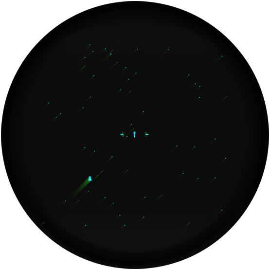
The gravitational star at the very center of Spacewar!'s concentric setup (Emulation, Spacewar! 3.1)
Credits: Norbert Landsteiner 2014
BTW: ▶ You can play here the original code of Spacewar! running in an emulation.
While just a single short spinning line, the gravitational star (or the heavy star, or just the Star, sometimes also called the sun), was maybe the most important visual element of Spacewar!. In order to understand this, we have to recall the actual setup, in which the game would have been experienced: While the PDP-1's scope, the DEC Type 30 CRT display (initially named "Type 30 Visual CRT Display", but soon called the "Type 30 Precision CRT Display") would paint any content on a perfectly square display area, it exposed a circular tube, which was contained in a distinctive hexagonal housing. A concentric layout that would be further emphasized by the circumference of the bright metal border of the central extrusion of its bezel. Further, the Type 30 CRT featured a P7 compound phosphor that sported dual characteristics, a bright blue activation and a long sustain in a dimm yellowish green, which would provide for the iconic trails that were drawn by any moving objects. (P7 phosphor was a characteristic feature of the PPI scopes of mechanical scan radar — which had also been the original purpose of the Type 30 CRT's tube.)
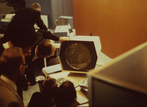
The wonders of Spacewar! on a DEC PDP-1's Type 30 CRT display.
Credits: Publicity photograph; Computer History Museum (CHM), Catalog No 102652458
This essentially concentric setup was echoed by the game itself: Emphasized by the fading trails, the ships would be drawn by gravity to the very center, just to explode in a pictoresque cloud of pixel-dust, or would swirl around the center thanks to the wonders of Netwon's law. And in the very midst of it, there would be the Star, not just a bare line, but a mysterious bunch of fading, pulsating, spinning flashes, quite like a magic eye, the very embodiment of the natural magic of gravity, Spacewar!'s governing feature of game play, — by this providing both a visual focus and the very glue between the game's appearance and its internal mechanics. Reason enough to make this a prominent number two in our journey through the realms of Spacewar! code.
As usual, before providing some actual code, we'll include the standard credits first, which are also providing some important historical data:
Spacewar! was conceived in 1961 by Martin Graetz, Stephen Russell, and Wayne Wiitanen. It was first realized on the PDP-1 in 1962 by Stephen Russell, Peter Samson, Dan Edwards, and Martin Graetz, together with Alan Kotok, Steve Piner, and Robert A Saunders. Spacewar! is in the public domain, but this credit paragraph must accompany all distributed versions of the program.
The Code
The code for drawing the gravitational star is to be found near the end of the first of the two main parts of Spacewar! (the "library part"), just between the code of Dan Edwards' outline compiler for displaying the spaceships and Peter Samson's Expensive Planetarium. (As usual, we are referring to version 3.1.)
/display a star

define
	starp
	add \bx
	swap
	add \by
	swap
	ioh
	dpy-4000
	terminate

blp,	dap blx		/star
	szs 60
	jmp blx
	random
	rar 9s
	and (add 340
	spa
	xor (377777
	dac \bx
	lac ran
	ral 4s
	and (add 340
	spa
	xor (377777
	dac \by
	jsp bpt
	ioh
blx,	jmp .

bpt,	dap bpx
	random
	sar 9s
	sar 5s
	spa
	cma
	sal 3s
	add (bds
	dap bjm
	cla cli clf 6-opr-opr
	dpy-4000
bjm,	jmp .
bds,	repeat 20, starp
	szf 6
bpx,	jmp .
	stf 6
	cma
	swap
	cma
	swap
	jmp bjm
This would be called at the end of the main loop of the program, in the second line of this short piece of code, just after calling the Expensive Planetarium to draw the background:
mq3,	background	/ display stars of the heavens
	jsp blp		/ display massive star
	count \mtc, .	/ use up rest of time of main loop
	jmp ml0		/ repeat whole works
Further, the code above makes use of two macro definitions, one to be found in the common MIT macros (swap), the other (random) being defined near the top of the first part of Spacewar!:
	define swap
	rcl 9s
	rcl 9s
	term
	define
random
	lac ran
	rar 1s
	xor (355670
	add (355670
	dac ran
	term
where the location labeled ran (used by macro random) is located prominently at the end of the heading table of "constants" (at the octal address 31):
ran, 31, 0 / random number
(For the basics of PDP-1 instructions and Macro assembler code, please refer to part 1. We'll repeat the semantics of the instructions as we're encountering them.)
To Catch a Coder — A Who Done It on the PDP-1
Before actually diving into the code, there are some things which can be addressed at a more general level before. The most thrilling one of these is probably the question, who actually was the contributor of this piece of code. Like the "Expensive Planetarium", we've seen before, this is quite an isolated piece of logic, and it's in the same part of the listings, directly neighboring other pieces of code that could be qualified as "contributions". So, who was it?
We can tell at first sight that this is not another contribution by Peter Samson, whom we met before. It's in a totally different coding style. So, could this be a piece by Steve Russell? Hardly. Steve Russell is generally showing himself as a master of tables and vectorized approaches all over the code. This shouldn't be of much suprise, since this is the same Steve Russell who made Lisp an actual programming language, rather than just the mathematical notation it was before. It's true, there's some kind of an vectorized approach in this code, too, namely the part actually drawing the line by a table of commands rather than by a loop (we'll see later), but it's not really Russell's style. Also, there's this outcoupled code in a macro, a thing we never see in those parts of the code that can be attributed to Steve Russell without doubt. The parts closest in style are the outline compiler for drawing the spaceships (located in the listing immediately before this) and the code for calculating the gravity. We know from the writings of J.M. Graetz that these were done by Dan Edwards, who was also the "heavy numbers" guy of the Hingham Institute Study Group on Space Warfare. (We know of Steve Russell's reluctance on this side of the job, who didn't feel like doing numerical analysis — "I pleaded innocence of numerical analysis and other things" — and Dan Edwards was the man to the rescue.) For this, the parts by Dan Edwards are also exhibiting, what may be called the densest logic to be found in any of the parts of Spacewar!. And in deed, this piece of code is showing some similarities to the one of the outline compiler. But we're left with very few display code that could be attributed to Steve Russell exclusively, so there isn't much for comparison. Also, before there was the outline compiler, there would have been probably some kind of an outline interpreter, presumingly by Steve Russsell, and there might be traces left in the code of compiler. But there's an instruction that could turn into some evidence for the authorship of Dan Edwards on the star drawing code, nameley the "dpy-4000" instruction, followed by an "ioh", a construct which is ocurring else only in the outline compiler directly above.
The Ominous dpy-4000 Instruction
The PDP-1's dpy instruction, used for displaying a dot on its scope, was one of the most complex one that could be deployed in numberous ways. This was owed to the concept of a single iot (i/o transfer) instruction that would manage all in- and output passing from the PDP-1 to any peripheral device or back from these into the computer respectively. The two lowest nibbles (the two lowest octal numbers representing bits 12-17) would specify the device and the two middle one (bits 6-11) would be used to pass any parameters to the device. The presence of the i-bit (bit 5) would instruct the computer to pass a signal to the device that would demand a completion signal to be sent back to it as soon as the device had finished the task. With some commands, the computer would halt and wait for the device to send the signal, with others, the program was expected to check and clear this signal by an "iot i" instruction (commonly referred to as ioh, octal 730000) anywhere in the following code. In case the device would have returned the completion signal at this time, this would be without effect to the program. But, if the device wouldn't have returned the signal yet, the computer would halt its operations to wait for the signal to be returned.
As for the dpy instruction, this was encoded in the Macro assembler including the i-bit. For this, there are two distinctive flavors of the basic dpy instruction: "dpy -i", octal 720007, and the bare dpy instruction, octal 730007. With "dpy-i" displaying a dot was essentially a fire and forget operation — issue the command and the display will do all the rest. But with the i-bit set, the computer would halt and wait for the completion pulse, returned by the Type 30 CRT display approx. 50 microseconds later (at which point any input from the light pen would have been processed, too). Waiting for the display to have actually activated the dot made sense for an interactive application using the light pen, else it was generally recommended to use the "dpy -i" instruction (or the synonymous "iot 7").
As for the 6 control bits (or x-bits) passed to the display, there is suprisingly few documentation on the actual workings of the dpy instruction. (Which is really startling, given that the DEC manuals and documentations were of a quality that was setting standards for the whole industry.) In fact, we have to fast-forward to August 1968, until we may find an extensive memo "PDP-35 / PDP-1 Instruction List" (DEC, Aug 1968) and as far as September 1971 — a full decade after the release of the machine — for a revised version of this memo, namely "PDP-35-2 / PDP-1 Instruction Manual / Part 3 -- iot Operated I/O Devices" (DEC, Sep 1971), for some definitive information. And this is, was the revised memo (PDP-35-2, pt. 3, p.5) has to say on the dpy instruction regarding the x-bits and the i-bit:
The dpy instruction (73cb07) causes one point to be displayed on the scope. (...) The three "b" bits control the brightness -- 4 is visible to photomultiplier tubes only, 7 is barely visible in a dark room, 0 is normal, and 3 is brightest. The "c" bits control the centering. 0 makes the origin in the center of the scope. 1 puts it at a the center of the bottom edge. 2 makes the origin be half way up the left edge, while 3 puts it at the lower left corner.
A dpy (that is with the i-bit on) takes 50 microseconds to complete. dpy-i (iot 7) does not wait for the scope to complete. Since it is impossible to activate the scope too fast, one normally executes iot 7 instructions. This allows the program to continue while the scope is running.
So, what does this mean for deciphering "dpy-4000"? As we already know, the Macro assembler was simply adding up all expressions in a line to make the resulting instruction code. For this, "dpy-4000" is "730007-4000" or 724007, or, in other words: no i-bit, a 4 in the c-bits, and a 0 for the default brightness in the b-bits. Since only the two lower bits of the c-bits are of relevance, this should be whithout any effect on the centering, and for all we know, this should be just a rather extravagant way of issuing a "dpy-i" or 720007 instruction. Emprically we know that "dpy-4000" has no effect on the origin of the display, since the gravitational star is displayed at the center of the screen. But we also know from empirics that this instruction is causing the display to return a completion pulse, otherwise the following "ioh" would cause the machine to halt and wait for ever and there would not be a Spacewar! at all.
But, we may ask, why is this construct using ioh at all, since the computer would either be waiting just after having sent the command to the display (as with the i-bit set) or would commence and ignore the display (as without the i-bit) — at least, based on what the documentation is telling?
To our rescue, there is the arcane "PDP-1 Input-Output Systems Manual (Preliminary Manual)" (FP-25, DEC, date unknown), providing finally specific information on bit 6, set by "dpy-4000". While there isn't much information specific to the usage of the x-bits regarding the dpy instruction in the Preliminary Manual, it makes a more general statement (FP-25, p.8) on the combined usage of bits 5 and 6 with the iot instruction, a usage that appears to be specific to the various tape commands in later manuals:
TABLE I
In-Out Transfer       Wait for Completion Pulse     Enable/Disable-
Command Bits          for Restart/Continue          Completion (Done
5         6           without wait                  Pulse Signal
––––––––––––––––––––––––––––––––––––––––––––––––––––––––––––––––––––––

0         0           Continue, no wait             Disable
0         1           Continue, no wait             Enable
1         0           Wait, then continue           Enable
1         1           Wait, then continue           Disable


   Bits 5 of the in-out transfer command designates whether the program
is to wait for a completion pulse before continuing. The exclusive
or of bits 5, 6 of the command specify whether the completion pulse
return signal is to be enabled or disabled.
A bit later, the Preliminary Manual provides a small demonstration program for the use of the display instruction, including the following lines to draw a line from inside a loop (comments are here started by comma):
loop	730000	,dummy - halt till previous completion
	724007	,display a point/computer proceeds
	...
This is followed by the commenting statements (FP-25, p.9),
(...) The program commands a point to be displayed, (without disabling the completion pulse), proceeds with the calculations, then finally gives a syncronizing "wait" instruction which synchronizes the display.
The only case not included above, but mentioned in Table I, is the case of bits 5 and 6 both zero. Here, the program does not halt the and the completion pulse of the device is enabled. Thus, the program must only refrain from giving the display commands too frequently.
The technique of inhibiting completion is used when several devices are operating concurrently. The inhibit command completion is used with the sequence break system.
So, finally, we know by definition what the "dpy-4000" / "ioh" construct is doing and where this pattern of usage originated, even, if the Preliminary Manual isn't in line with later documention regarding recommendations on general usage.
Note: A careful reader may have observed an inconsistency in the specs as provided in the Preliminary Manual, 734007 with both bits 5 and 6 set, would cause the computer to halt and wait, but would not command the display to return a completion pulse — a PDP-1 equivalent to "halt and catch fire" (but without actually burning any circuits).
*****
But — wait — isn't this just vasting some precious CPU-cycles, waiting to synchronize, here, where there is no light pen involved at all? At least, in the light of later documentation, recommending a "dpy-i" in general, as used elsewhere in the Spacewar!-code?
In order to provide an answer to this, we have to dig a little deeper, right to the dirty, noisy low levels of analog equipment. The Type 30 CRT display was some serious piece of hardware that was operating on a considerable speed: "Discrete points may be plotted in any sequence at a 20 kilocycle rate (one point every 50 microseconds)." (DEC brochure "Precision CRT Display / Type 30", F-13(30) 5/64, DEC, 1964, p. 2). In order to do so, it had to drive high voltages to position the magnetic deflections at the required speed and at some accuracy (+/- 3% of the raster size), and this had some serious effects (not at least to the price, as the Type 30 CRT came at USD 35,000 — more than a quater of the price of a standard PDP-1 —, but also, the manual is unmistakable in its warning not to ever operate the scope without its cooling fans on, since this would inevitably burn its expensive deflection circuits).
Investigating the maintenance manual "Precision CRT Display / Type 30E" (F-15(30E) DEC, Dec. 1963), which is in fact covering the types 30A, 30E and 30M, we find the following details on the display procedure: The display would take a digital signal, would convert the 10-bit coordinates to analog levels to drive the magnetic deflectors to position the beam, would decode the brightness information to the accurate analog level, and would then open its gates to fire (unblank) its cathode beam for a precise 10 microseconds to activate a spot of 0.015 inches size at the front facing phospor, followed by the DDP (Display Done Pulse) pulse, triggering any completion signal. Since we're dealing with analog processes, altering the display location equaled to a step in analog address voltage, and, with the voltage levels involved, the abrupt change would cause some ringing in the deflection coils, resulting in an oscillation of the intensified spot. In order to address this, the deflection coils were damped by a compensation network circuit. But this would not stabilize the final output value used to address the beam completely, rather, it would purposely overshoot the address by a fixed amount or undershoot it by a quantity that was dependant on the previous address value. (This was due to the coupling of the focus coils and the deflection coils, resulting in a bit of hysteresis.) The manual even provides a timing diagram, giving the characteristics of the compensation network:
DEC Type 30 CRT display deflection compensation characteristics
We may assume that this might have had some effect, when it came to drawing the tiny line segements of the spaceships that were drawn in rapid succession in some sharp angles to produce the outlines. It would have made some sense for the code produced by the outline compiler to wait in order to allow the compensation circuits to cool and to get the most accurate image of the tiny spaceships by avoiding the uncertainty of the over- and undershoots. At least, this is the only reason, I could think of, for using the combined "dpy-4000" and "ioh" instructions. (Further, I would have to stress that this is an assumption based on an interpretation of the manual only.) But, as for the code drawing the star, which is advancing the beam at a constant speed in a constant direction most of the time (as we'll see), this wouldn't have much effect. Also, there are some instructions in between the dpy and the ioh and this wouldn't cause much of an extra delay (in fact about 10 microseconds). So, regarding the star-code, it's much more like a friendly idiosyncrasy of the code, and, while being based on early documentation, much more on the style side than on the functional side, making this a first class evidence in our case.
(Opposed to the above attempt to explain this usage, we may argue that the deflection coils would have been loaded anyway, regardless of how much time was passing between display commands, and that the timing of the compensation network would rather give the reason for the maximum display rate of 50 microseconds or 20,000 dots a second. But, at least, there would have been some reason for the Preliminary Manual recommending to control the rate of display commands. If this wasn't related to through-put — "it is impossible to activate the scope too fast" —, it would have probably been related to performance. Anyway, we may conclude that the author of the outline-compiler and of the star-display was referring to the Preliminary Manual and the others weren't neccessarily doing so.)
EDIT: On second thought, what does, "it is impossible to activate the scope too fast", really mean? Sure, it means you can't ruin the display, but what will happen to the dots to be drawn? Since there's no notion of any I/O buffers for the display, firing dpy instruction in rapid succession would probably mean skipping those display commands that were executed while the display was still busy. Thus the construct dpy-4000 — ioh would make sure that all the dots would be actually drawn. (And thanks to the timing diagram above, we also know, why we would have to wait.)
But, according to latest informations, the display is just likely to be blurry, when addressed too fast, due to the ringing of the deflection coils.
Conclusions
So, returning to our Who Done It, was it Peter Samson in the library using the candle stick? No way. (See his use of "dpy-i".) Was it Steve Russell in the conservatory using the wrench? Probably not. (In the few places, where Steve Russell's code is issuing display commands, it makes use of a macro resulting in the insertion of a "dpy-i" instruction.) So, was it Dan Edwards using the Flexowriter in the Kluge Room? Quite plausible. (Various parallels to the outline compiler code and especially the use of the "dpy-4000" – "ioh" construct render him the prime suspect.) — That much about our Code-Cluedo.
Incidentially, our findings are seconded by an article in MIT Technology Review from June 2005 by Corie Lock:
Dan Edwards programmed a sun in the middle of the screen that exerted gravitational pull on the ships.
(Lock, Corie, "The Start of Computer Games", MIT Technology Review, 1 June 2005)
But most of the information provided in this article seems to be drawn from the writings of J.M. Graetz — and these are apparently addressing the code for calculating gravity only:
This star has a strong effect (which approximates gravitation) on the two spaceships. The program for this was also written by Daniel Edwards. In the final version of SPACEWAR! he is going to provide an improved integration to eliminate some of the more unexpected, albeit interesting, properties of the "heavy star."
(Graetz, J.M., "Spacewar! Real-Time Capability of the PDP-1", Decus Proceedings 1962)
(The "final version" containing a new code for gravity advertised in this passage would eventually be Spacewar! 4.0.)
In "The Origin of Spacewar" (Creative Computing, 1981) J.M. Greatz provides some details on the social interaction involved:
Russell: "Dan Edwards was offended by the plain spaceships, and felt that gravity should be introduced. I pleaded innocence of numerical analysis and other things" — in other words, here's the whitewash brush and there's a section of fence— "so Dan put in the gravity calculations."
The star blazed forth from the center of the screen, its flashing rays a clear warning that it was not to be trifled with. Its gravity well encompassed all space; no matter where you were, if you did not move you would be drawn into the sun and destroyed. (As a gesture of good will towards less skillful or beginning players, a switch option turned annihilation into a sort of hyperstatial translation to the "anti-point," i.e., the four corners of the screen.)
At least, J.M. Graetz isn't that clear, if this contribution by Dan Edwards would have also included the display code, or would merely have been the code for the influence of gravity on the spacships. With a bit of conservative caution, we'll have to admit, that there might have been some generalization involved in the MIT Technology Review's account, suggesting that Dan Edwards would have done all the coding related to the sun.
In fact, the part in the MIT Technology Review appears to be a rephrasing of a passage in Steven Levy's "Hackers – Heros of the Computer Revolution" (1984/2010, p.53):
Another programmer named Dan Edwards was dissatisfied with the unanchored movement of the two dueling ships. It made the game merely a test of motor skills. He figured that adding a gravity factor would give the game a strategic component. So he programmed a central star a sun in the middle of the screen; you could use the sun's gravitational pull to give you speed as you circled it, but if you weren't careful and got too close, you'd be drawn into the sun. Which was certain death.
Again, we might not be too sure about this, especially, if this would be based solely on the writings of J.M. Graetz. Without knowledge of any additionaly sources, we would have to consider to stick to a conservative view.
So, in conclusion, is there hard evidence of Dan Edward being the author of this piece of code?
To quote the authors of Spacewar!, *mumble*.
(Various sources, originally regarding the absence of any influence of gravity on the torpedoes.)
But we may put on record that a comparative reading of the source is at least suggesting it.
Update, April 2021
Dan Edwards recounted at the Smithsonian presentation on the occasion of the Spacewar! team recieving the AIAS Pioneer Award on November 29, 2018:
As I looked at the game essentially it had this star in the middle, while it had no effect on the gameplay itself. I thought it would be better to use that to provide the gravity and put something out of the immediate, direct control of the game player (…)
So there was a central star quite early on, before gravity had been introduced to the game. However, it had been added for purely aesthetic reasons, as a perfect ornament!
Update, May 2021
Moreover, according to Peter Samson, the central star was created by Don Eastlake (citing Don Eastlake as the source). Steve Russell, on the other hand, recalls that he and “and many other people tinkered with the star and the explosions to make them better”, and would “hesitate to ascribe authorship to an one person, but happy to accept all as contributors.”
Personally, I think, considering the persons involved, when these had been admitted to MIT (Spacewar had been conceived and programmed before this), and the rather basic design of that star given in the description (a composition of static lines at an angle, much like on the LINC port, for which this may have provided an example), that this may have rather been related to the PDP-4 port that happened a year later. (Notably, the PDP-4 looks much like the PDP-1 and it may be easy to confuse them.)
So the authorship of the central star remains a bit of a mystery.
Swapping Myths
Another topic that might be addressed here, before jumping right into the code, which is of more general interest than just regarding to this single piece of code, is the common notion of resources being that scarce on the PDP-1 that various nifty tricks had to be employed to get the code running at all, like using the same address to contain two separate values and swapping them in and out. But there isn't any evidence for this in the actual code. The notion of swapping values is probaly due to the use of the macro swap, which we'll encounter here for the first time and which is frequently used in the context of display operations. (Or it might be owed to the use of other shift and rotate instructions all over the code for scaling values. Another canditate would be the code for parsing the control-input that was in deed encoded as a bit-vector. But swap is the prime suspect for having caused these rumors.)
	define swap
	rcl 9s
	rcl 9s
	term
In order to understand this, we have to know that the PDP-1 lacked an instruction to exchange the values of the accumulator (AC) and the i/o-register (IO). Instead, it provided a set of shift and rotate instructions which coupled the two registers to form a single 36-bit register and would manipulate its conentents. "rcl 9s" rotates the contents of this meta-register 9 bits to the left ("9s" being a predefined constant representing 9 bits set, as in octal 777). Since a rotate or shift by 9 bits in any direction was also the maximum amount, this instruction had to be repeated in order to perform a full swap of the register's contents by a 18-bits rotation. That's all what swap actually did, and it came handy, when there would have been any arithmetics to be applied to the y-coordinate of a dpy instruction (to be supplied in the IO register). By a swap, the registers would exchange their values and the y-value would be processed in the accumulator. Another swap would transfer it back to IO, with AC being ready to provide the x-value.
PDP-1 Memory
So, how scarce were the resources of PDP-1 in reality? How tight were the memory conditions?
Let's have a look at the memory map of Spacewar! 3.1 (addresses are octal):
0000 - 0002	reserved for sequence break system
0003        	jump vector to sequence break flush (0061)
0004       	default start address (jump to configure to use control boxes)
0005       	alternative start address (jump to configure to use the test-word)
0006 - 0031	table of essential game constants (for hacking)
0032 - 0037	free, space for patches (dedicated to alternative control input)
0040         	instruction vector for alternative control input
0041 - 0060	free, space for patches
0061 - 0065	routine to flush sequence breaks
0066 - 0155	sine-cosine subroutine
0156 - 0245	BBN multiply subroutine
0246 - 0305	integer square root subroutine
0306 - 0403	BBN divide subroutine
0404 - 0647	outline compiler
0650 - 1127	display routine for gravitional star
1130 - 1443	Expensive Planetarium (display routine)
1444 - 2734	Spacewar! main code
2735 - 2744	outline data spaceship 1
2745 - 2751	free
2752 - 2761	outline data spaceship 2
2762 - 2765	free
2767 - 3111	constants
3112 - 3222	unused (space left by assembler)
3223 - 3275	variables
3276 - 3475	free, space for patches
3476 - 3772	space reserved for the objects table
3773 - 5245	code produced by the outline compiler goes here
5246 - 6077	free (unused)
6077 - 7750	Expensive Planetarium (star-map data)
7751 - 7777	free (used by bin-loader)
As we can see, there's ample of free space left, about a quater of the PDP-1's standard memory of 4096 18-bit words. There's no chance of actually running low on space for the code or the various variables. Memory wasn't a tight resource, the scarce article being runtime. — There was definitely no need for spending CPU cycles on swapping operations, just to store two or more values in a single memory register. In fact, there was that much memory left that you could run another program, the ddt debugger, in parallel. (You would had have to configure the game to use a single outline for both of the ships by setting the contsant ddd to zero — as we will see in a later episode — in order to preserve some space, but it could be done.)
In order to give some idea of the resources actually available on the PDP-1, let's compare a simple operation, as the subtraction of two values and storing the result, with the operations of an 8-bit CPU, like the late 1970s/early 1980s 6502 CPU, popular on the Apple II and (in its 6510 flavor) on the C64. To not to be unfair to the 6502, we won't go for 18 bit values, but use a real world example, like proccessing a 10-bit coordinate.
Let's have this done by the PDP-1 (all values octal):
2000   lac 2003      / 2 cycles
2001   sub 2004      / 2 cycles
2002   dac 2005      / 2 cycles
2003   507           / operand 1
2004   412           / operand 2
2005   0             / result
This adds up to 6 addresses in total and 6 CPU cycles at 5 microseconds, to be completed in a total of 30 microseconds.
Enter the 6502 (all values hex):
$2000   lda $2013    ;3 bytes, 4 cycles
$2003   sec          ;1 byte,  2 cycles
$2004   sbc $2015    ;3 bytes, 4 cycles
$2007   sta $2017    ;3 bytes, 4 cycles
$200A   lda $2014    ;3 bytes, 4 cycles
$200D   sbc $2016    ;3 bytes, 4 cycles
$2010   sta $2018    ;3 bytes, 4 cycles
$2013   $47          ;operand 1 lo-byte
$2014   $01          ;operand 1 hi-byte
$2015   $0A          ;operand 2 lo-byte
$2016   $01          ;operand 2 hi-byte
$2017   $00          ;result lo-byte
$2018   $00          ;result hi-byte
In comparison the 6502 requires 25 memory locations for the same operations and will spend 26 CPU cycles on this, equalling (at a clock speed of 1 MHz) 26 microseconds. (Doing the same with the full 18-bit values of the PDP-1, would require a total of 37 memory locations and 38 cycles/microseconds for the 8-bit CPU.) In case we would extend the example to multiplications and divisions, the PDP-1 would be running circles around the 6502, thanks to its high-precision multiply/divide steps.
Extrapolating this, the 4096 18-bit addresses equaled much more 17 or 18 K on a 8-bit machine than just a mere 4 K, with a runtime performance that was much like the microchips' performance. Considering the space required to maintain a bitmap (another 8K at least on the C64 at a much lower resolution, not to mention any off-screen bitmaps for a flicker-free display) and that there wasn't a ROM or any space reserved by the system, this effictively equaled like 24 - 32 K of memory (quite like the amount of RAM available to the user on the Aplle II or the C64 respectively). And as we know from the prospering video games industry of the late 70s and early 80s, this is plenty for driving a video game written in assembler code. (At least, if you know the tricks to squeeze some runtime out of the machine — and Spacewar! pioneered some of these.)
This said, there was still a limiting factor, namely the time required for a display command to complete (50 μsec), making tensely timed display code the decisive factor in Spacewar!-programming.
(With the costs of memory required to maintain a display bitmap then amounting to astronomic ranges, we face the classic time-versus-space dilemma on the hardware side. While the x/y point plotting displays were the obvious solution to the memory problem, they came at a price in terms of completion time for each single dot to be displayed.)
Whith a phew! we now may have a look at the code, finally.
The Code, Again
Let's start with the main routine, to be called as a subroutine at label blp:
blp,	dap blx		/star
	szs 60
	jmp blx
	random
	rar 9s
	and (add 340
	spa
	xor (377777
	dac \bx
	lac ran
	ral 4s
	and (add 340
	spa
	xor (377777
	dac \by
	jsp bpt
	ioh
blx,	jmp .
As usual, the code starts with a dap (deposit AC in address part) which will store the return address (placed in the contents of the accumulator by the previous jump-sub instruction) in the location labeled blx, leaving the instruction part (the highest 6 bits) as is. When executed, this instruction will cause a jump to the return address, what ever this might be.
The instruction "szs 60" (skip on sense switch zero) conditionally skips the next instruction, if sense switch 6 (the number of the sense switch to be specified in the second lowest nibble, hence 60) is not set. If sense switch 6 is set, the jump to blx immediately following to this will cause an early return. Thus, if sense switch 6 is deployed, there is no sun.
The pseudo instruction random is inserting the macro with this name in place. We'll have a look at this later, the important part being that this is recalculating a 18-bit random number in location ran which is also left in the accumulator. The instruction "rar 9s" rotates the fresh random number in the accumulator by 9 bits to the right, and the following instruction "and (add 340" performs a logical AND with the value of the constant given in the expression "add 340" (octal value 400340) on this.
The following spa (skip on accumulator plus) skips, if the result would be positive (meaning the sign-bit in bit-0 not set). Else, the next instruction "xor (377777" will be executed, performing a logical exclusive-or by the value of the constant 377777 on this. "dac \bx" then stores the result of the previous operations in the variable bx.
The next instructions load the radom number back from location ran to the accumulator (by "lac ran") and repeat the operation, with the only difference of the value now being rotated 4 bits to left (by "ral 4s") and finally being stored in the variable by.
This is followed by the a jump to the soubroutine at label bpt, a final, sole ioh to wait for the display (apparently there's some "dpy-4000" executed at bpt) and exits at label blx with a jump to the return address.
Let's recapitulate:
Obviously this piece of code is preparing and scaling a random value to be used for some x- and y-value, stored in the variables bx and by respectively. The heavy work is done by the subroutine at bpt, and after last synchronizing by ioh (obviously cleaning up a pending display wait state), we're done and return.
But how are these two factors scaled? They are not scaled by the rar and ral, these are just making sure that different parts of the same random value are used, making these independant factors. The scaling is done by the and. — Let's have a closer look:
The expression "add 340" is a nifty way of saying, we're just interested in bits 10-12 (counting from the most significant bit at the left) and the sign bit. Since the bare instruction add is octal 400000 with only the highest bit set, it is representing the sign bit. In fact, this expression may seem arcane, but it is perfectly expressing what is meant, even better than the full numerical representation of 400340. At least, if we would speak PDP-1-ish.
So, we have reduced the random value to three bits in a somewhat odd position and preserved the sign bit. But, if the sign bit would be set, this isn't a well-formed 1's compliment negative number, as used by the PDP-1. This is, what the two following instructions are cleaning up: The instruction "xor (377777" flips all bits, but the sign bit, transforming this into a perfect negative number to be used by the PDP-1's arithmetics.
Since we're really courious, what this factors would be for, we're quickly scanning the rest of the code for bx and by and are finding them both in the macro starp:
define
	starp
	add \bx
	swap
	add \by
	swap
	ioh
	dpy-4000
	terminate
First, the contents of bx is added to the value in the accumulator. Then, the macro swap is inserted. We know already, what this one is doing, it exchanges the values of the accumulator and the IO register. Then the value in by is added to the value that has previously been in the IO register and the two registers are swapped again. This is followed by the combination "ioh" – "dpy-4000", the very combination we know from the Preliminary Manual, from the example code for drawing a line from inside a loop. The ioh will wait for the completion pulse following a previous "dpy-4000", but the time passing is used to do the calculations on the two registers. The final "dpy-4000" will actually display the point, at the locations provided in bits 0-9 of the accumulator (for X) and bits 0-9 in IO (for Y) and will commence with the completion pulse pending.
This is obviously a piece of code for displaying a single dot, which is advanced by the two factors bx and by along the x-axis and the y-axis respectively. This also provides the explanation for the specific scaling of the two factors: Bits 10-12 are the three highest bits immediately below the bits used to communicate the display coordinates. This is equal to scaling the factors to a decimal range of -0.9 to +0.9 and using the integer part of the result of the addition. The display coordinate will advance by an amount that is just less than a single coordinate step. The reminder in the lower 8 bits is simply ignored for the display purpose and the coordinates will advance along a constant slope at less than 45° (mirrored by any of the two axes).
So, we already know, how a dot is drawn as a part of a line and how the slope is set up. Let's see, which kind of logic is driving the whole thing:
bpt,	dap bpx
	random
	sar 9s
	sar 5s
	spa
	cma
	sal 3s
	add (bds
	dap bjm
	cla cli clf 6-opr-opr
	dpy-4000
bjm,	jmp .
bds,	repeat 20, starp
	szf 6
bpx,	jmp .
	stf 6
	cma
	swap
	cma
	swap
	jmp bjm
Since this is called as a subroutine, the initial dap is depositing the return address, as usual, in the address part of the jump to return, in this particular case at bpx. Then the macro random is inserted another time, calculating a fresh random value and putting it in location ran and also leaving it in the accumulator. The two sar are shifting this (decimal) 14 bits to the right (this have two be two instructions, because the maximum amount of a single shift is 9 bits). By this, the random value is reduced to the 3 lowest bits with the sign-bit preserved. So there's currently a value in the range of -7 to +7 in the accumulator. The two following instructions, spa and cma equal to making this an absolute value: spa skips on a positive value, in case the value would be negative, the following cma (compliment AC) flips the bits in the accumulator for a 1's compliment. Thus, there is now a positive 3-bit random number in the accumulator.
This value is then shifted 3 bits to the left, multiplying the value by 2^3 (or decimal 8), to which is then added the constant expression "(bds".
Wait, what was this? Let's see: bds is simply a label, designating the location, at which there will be inserted (octal) 20 (decimal 16) incarnations of the macro starp. We just calulated an offset in the decimal range 0..7 multiplied it by 8 and added this as an offset to the address of label bds. This is now inserted into the address part of the instruction at bjm by "dap bjm". Since the op-code of the instruction is a jmp and the macro starp happens to be exactly 8 instructions long, executing the jump at bjm will skip any of up to 7 of this array of starps. Seems, we've just set up a random length of the line to be drawn, anything from 9 to 16 advances by bx and by long.
(Note: Veteran C programmers might recognize Duff's device in this construct.)
Fine, but what is "cla cli clf 6-opr-opr"? The various instructions of the operate group, sharing a common op-code in the highest 6 bits, could be combined to be executed as a union in a single step (or CPU cycle). This is simply 3 operations in a single instruction, and since each of them had the bits for the op-code set and the assembler was performing an addition, the redundant parts, as given by opr, the bare op-code common to this group, had to subtracted for any of the exceeding ones. This adds up to the numeric instruction 764206, but all we have to keep in mind is that this is performing a cla (clear AC), a cli (clear IO), and a "clf 6" (clear program flag 6) at once. Thus, we reset both AC and IO to zero, or rather, in the context of the dpy instruction, we set them to the center of the screen, and we clear flag 6, probably to be checked later in the code. (As mentioned in Part 1, the program flags were an array of user addressable flags that were also used as state indicators with some I/O devices.)
The following "dpy-400" is both putting an initial dot in the very center of the screen and is demanding the pending completion pulse, the first of the incarnations of starp will be waiting for. Finally, the jump at bjm jumps right into the row of starps at our previously calculated offset in order to draw the line.
After executing all the starps, we will have drawn a nice random line, pointing in any direction from the very center of the screen, notably whithout the help of any loop construct. Thanks to this vectorized jump, the code will speed as fast as possible through the starp, without any further checks. (Remember, memory was not the scarce article)
But we're not finished by now. To repeat the remaining part (just to have it at a screen's length):
	szf 6
bpx,	jmp .
	stf 6
	cma
	swap
	cma
	swap
	jmp bjm
In case program flag 6 would not be set, "szf 6" (skip on flag zero), we would skip the jump to the return address. Since we made sure that this would be cleared before, we're not done yet. After setting program flag 6 by "stf 6", the following cma (compliment AC) flips the bits in the accumulator, thus performing a 1's compliment. The swap rotates AC and IO, just to compliment the value previously in IO by the next cma, and the final swap rotates both registers in place.
In order to understand this, let's recollect what was done before: By drawing the line, the coordinates in the AC and IO registers were now pointing to some spot less than 16 display location away in any direction from the center. Since the origin is located at the center, inverting the coordinates (thus changing the sign) will now have them pointing to a spot exactly in the opposite direction. We're now placed, were we would have ended up, when drawing the line with the signs flipped. Thus, when we do another run using the same factors in bx and by, we're drawing the line back to the center, but mirrored by the two axes. We're actually complimenting the line at the other side of the origin, using the same slope and length. This is exactly what we'll do, when jumping back to bjm, the instruction with jump vector including the offset for the line length. Since we've program flag 6 set this time, this will be our second and last run and we'll take the jump to return address at bpx.
Random
The only piece of code, we haven't inspected yet, is the random number generator, as defined by the macro random:
	define
random
	lac ran
	rar 1s
	xor (355670
	add (355670
	dac ran
	term
I'm not qualified to express an educated opinion on this (or on any in the vast fields of numerical analysis). So I really can't say, how well this is performing as a random number generator. But the requirements for the purpose of the game aren't that high, anyway. Obviously, it does its job quite well. Let's see, how it does that well:
First, "lac ran" loads the contents of location ran into the accumulator, where it is rotated 1 bit to the right by rar 1s".xor (355670" flips most of the remaining bits, but the lowest 3 of them. Finally "add (355670" adds the the same constant to this and the result is stored back in location dap.
(Update: Since the difference between an addition and an XOR operation is just in the application of the ripple carry by combining both operations, we end up with just this isolated application of the carry. As it turns out, this piece of code came straight from a memo on the TX-0, where the application of the carry was a separate instruction, "cry". Compare TX-0 Computer, M-5001-19-1, “Some Useful Micro- and Macro Instructions”, MIT, Aug. 23, 1961, p. 4 — Thanks to Peter Samson for pointing this out!)
And here is the sequence as produced by the macro "random", starting from an initial seed value of zero:
States of ran over 8 consecutive runs starting from 0:

                           binary        octal

     ran (seed)      000000000000000000 (000000)

(1)  rar (>> 1)  =>  000000000000000000 (000000)
     xor 355670  =>  011101101110111000 (355670)
     adc 355670  =>  111011011101110000 (733560)

(2)  rar (>> 1)  =>  011101101110111000 (355670)
     xor 355670  =>  000000000000000000 (000000)
     adc 355670  =>  011101101110111000 (355670)

(3)  rar (>> 1)  =>  001110110111011100 (166734)
     xor 355670  =>  010011011001100100 (233144)
     adc 355670  =>  110001001000011100 (611034)

(4)  rar (>> 1)  =>  011000100100001110 (304416)
     xor 355670  =>  000101001010110110 (051266)
     adc 355670  =>  100010111001101110 (427156)

(5)  rar (>> 1)  =>  010001011100110111 (213467)
     xor 355670  =>  001100110010001111 (146217)
     adc 355670  =>  101010100001000111 (524107)

(6)  rar (>> 1)  =>  110101010000100011 (652043)
     xor 355670  =>  101000111110011011 (507633)
     adc 355670  =>  000110101101010100 (065524)

(7)  rar (>> 1)  =>  000011010110101010 (032652)
     xor 355670  =>  011110111000010010 (367022)
     adc 355670  =>  111100100111001010 (744712)

(8)  rar (>> 1)  =>  011110010011100101 (362345)
     xor 355670  =>  000011111101011101 (037535)
     adc 355670  =>  100001101100010101 (415425)
We may observe that this leaves (besides the simple shift, except rare occasions where an overflow occurs on the addition) the lowest 3 bits as-is. This also gives an explanation for the "ral 4s", right at the beginning, when we were preparing the y-factor in by. What seemed to be a bit of a luxury (since the bits used to set up the x-factor were located in the upper half of the bits, as made sure by the "rar 9s", why would we want to shift this just by a nibble?), is actually a necessity in order to get some valid random bits.
Note / Update
I guess, the macro "random" qualifies as a polynomial counter or LSFR (Linear Feedback Shift Register), meaning, it cycles over a fixed, but nonlinear sequence of values starting from a known seed value (mind that the value in "ran" is initialized to zero at the beginning of the code). This will be true for any code shifting and scrambling an input value which is consequentially fed back to it in the next call, as long as it doesn't "fall into the pit" of a minor cycle, which may consist in the worst case of just a single value. — A quick test shows that there's no such "pit" for the code to fall in, when starting with a value of plus zero. (However, investigating some out-of-sequence numbers for seeds, we find one with a value of octal 225241, resulting in the worst case scenario of a period of 1, and a handful of other ‘problematic’ seeds, which result in periods in the single digit range.)
Starting from zero, the sequence will run over a period 261,654 unique values until it eventually returns to the 2nd iteration with a value of octal 355670 — the modifying constant thus being also the reset value! — from a second-to-last value of 044217, skipping the inital seed of 0. This means, there are just 490 out of the 262,144 unique 18-bit values not included in this sequence.
Variations
In Spacewar! 4 the Star would see a small variation. It would be drawn by a dotted (or, depending on the slope, a dashed) line, rather than a solid one. This was achieved by setting the factors bx and by to a value that could actually advance the line by a full coordinate-step (the three bits in 700 are shifted 1 bit to the left, as compared to version 3.1, doubling the value of the two factors):
	random
	rar 9s
	and (400700
	spa
	xor (377777
	dac \bx
	lac ran
	ral 4s
	and (400700
	spa
	xor (377777
	dac \by
As a compensation for this, there were only (decimal) 8 repitions of the macro starp (with 16 of them in the original version of the code):
bds, repeat 10, starp
So, the star could be reduced to just to a mere dot, by skipping all, but one of them, while the maximum length would be about the same as in the 3.1. Besides the introduction of another bit of modualtion (the line would probably blend by the bleeding of the activated phosphor), it also squeezed some runtime out of the routine, by reducing the steps required to draw the line to 50% of the previous amount.
We could close here, but there's another mystery waiting, which also shows, how nifty this little piece of code for drawing the star actually was.
The Mystery of the Twin Stars
There is a version of Spacewar! 4, namely version 4.3, featuring a somewhat mysterious special mode to be activated by deploying sense switch 2. (You may explore this by this short-cut to the emulator with Spacewar 4.3! preselected and sense switch 2 set.) There is actually no historical reference to this, other than the source code to be found in a bunch of assorted listings. For this, we may start with a small description.
The mysterious "Twin-Star" in Spacewar! 4.3 (Emulation)
Credits: Norbert Landsteiner 2014
In this mode, Spacewar! isn't the same anymore, but this is all accomplished by some offsets in the display code: The Needle is tied to the center in the screen between a double sun. The Wedge is starting right at the lower left corner, drawn by gravity to the very center and the stars are moving somewhat oddly. When we explore this a little further, we'll see, that the Needle is rather pushing the whole universe, than being accelerated itself, when its thrusters are fired. Also, the center of gravity isn't at the center of the screen anymore, but is forming an odd pool in the space-time continuum at an apparently moving random spot. We may also observe that the exhaust flames of a thrusting ship are displayed at some odd location, the very spot, at which any torpedoes will appear, when fired. This location is giving in fact the true position of the spaceships, which are dislocated visually. For the hit detection, the display location is used, providing us the wierd experience of inhabiting to locations at the same time.
This displacement is achieved simply by subtracting the position of the Needle from the display position of the two spaceships, but not for the exhaust flames or torpedoes. Also, the Needle is moving the background starfield, too, by the same subtraction applied to the individual stars.
But how is the sun doubled to a twin-star system, located at the left and right of the screen's origin? Let's see:
	cla cli clf 6-opr-opr
	szf i 20
	jmp bjm-1
	sub ny1
	swap
	sub nx1
	dpy-4000
bjm,	jmp .
This version is actually inserting only a mere 5 instructions for this, right before the jump into the array of starps! How could this be?
For the benefit of historians, let's state first, that this is the code of Spacewar! 4.3, signed "5/17/63 ddp" (with "ddp" probably being Diamantis Drakos Preonas aka Monty Preonas). Another feature of these variants of Spacewar! is that these are picking up the approach to the intensities of the Expensive Planetarium, like it was initially coded in Spacewar! 2b, by modulating the apparent brightness by how often the stars were displayed. Also, this particular version featured a score display, quite similar to the one known from the scorer patch for Spacewar! 4.8, also to be seen in the patched version 4.1f, running at the CHM on the restored PDP-1. (But the code used for the score display differs somewhat from the code of the 4.8-scorer, also there are visual differences, like a separator line right in the middle of the screen.)
Note on the identity of "ddp": While Joe Morris recalls ddp's full name as "Demitrios D. Peronas" (compare Joe Morris, alt.folklore.computers, 5 April 2001), Peter Samson is confident of it being "Diamantis Drakos Preonas" — We're going here with Peter Samson.
As an alternative/complementary source the TMRC members list shows an entry for "Monty Preonas" as a member since 9/1960. Compare also "D. D. 'Monty' Preonas" mentioned as a computer programmer in "Experimental Investigation of Initial Surface Particle Motion Resulting From Small Subsurface Explosions in Dry Ottawa Sand", thesis by Major Floyd V. Kimberly (USAF), 1972; p. 6 and 7 (thanks to Devin Monnens for discovering the latter).
But back to our twin-star mystery:
The instruction "szf i 20" checks, if sense switch 2 would be set (the "i" inverting the condition). If not set, the following "jmp bjm-1" will take us to the dpy instruction, which is in the address just before bjm, and the star display will perform as usual. (An attentive reader may have observed that the szf is actually the instruction for checking a program flag. But, since both the szf and the szs instructions were in the operate group, they shared the same op-code and differed only in the bit position used to specify the switch or flag. If in the lowest nibble, it would be checking the flag with the given number, if in the second lowest nibble, it would be checking the according sense switch.)
If sense switch 2 is set, we're entering the just 3 instructions that are performing the modifications: The first sub subtracts the value in ny1 from the accumulator, which is then swapped to now contain the value of IO. From this, the value of nx1 is subtracted. Since both registers were cleared before, this is just adding an offset to the origin. Thus, the star will not be drawn in the center, but in the (compliment of the) position given in nx1 and ny1. Since we know that the two stars are drawn in a fixed position right and left of the center, we also know that nx1 is containing a fixed value and ny1 must be zero.
So we know, why there is an offset, but why are there two stars? The answer to this is to be found in the part after drawing the line by the array of starps: Since the code is inverting the display coordinates, it is also inverting the horizontal offset. So, the second part of the star, the part drawn outside in, will be drawn at the opposing side of the origin. And in deed, the two stars do not show the normal appearance: They are drawn by just half of the normal line, spinning around their respective centers at a random angle, but one being the mirror image of the other.
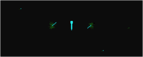
Closeup of the twin stars in Spacewar! 4.3 / sense switch 2 set (emulation)
Credits: Norbert Landsteiner 2014
Note/update: For a detailed analysis of Spacewar! 4.3 and its "Twin-Star Mode", see Part 9.
Note on the provenance of the "assorted listings" (CHM Catalog No 102664173):
These might be identical to the listings mentioned by Joe Morris in a Usenet alt.sys.pdp10 thread ("Re: KA10, PDP-1, museum", alt.sys.pdp10/cNG89mmlbK0/V0JPyn3Mg7sJ, in response to Al Kossow):
Late-breaking news: I found the listing binder in my office.  The
versions I've got are:

4.0, dated 2/2/63

4.2, dated 5/11/63 (with a torn scrap of greenbar where I
     scribbled notes about which buttons set which bits on
     the taper pin block (for the IOT instruction) from the
     drone controller someone bought from Eli's to run
     Spacewar on the PDP-1 on the first floor of building 20)
4.3, dated 5/17/63
4.4, dated 5/17/63 which still shows Monte's[sic] initials (ddp) but
     which vague memory says wasn't his update.  It may have
     been my hack, but I hadn't yet learned the tao of marking
     changed lines in programs  8-(

And, of course, Pete Sampson's[sic] STARS.
At least, we may note that this is identical to the contents of the "assorted listings". (The "assorted listings" are also containing a title punch routine for the paper tapes and a "spacewar game saver patch", apparently recording a game by continously saving the controls inputs and the contents of the pseudo-random number "ran".)
The listed programs, Spacewar! 4.0, 4.2, 4.3, 4.4, are signed ddp (D. D. "Monty" Preonas), and version 4.4 is still a work in progress.
(Please note that the provenance of the "assorted listings" is not confirmed by the CHM.)
*****
With all the mysteries solved, we may close for today.Next time, we'll encounter finally some of Steve Russell's code. — Stay tuned.
Next: A small intermission, regarding a recent update.
Vienna, June 2014
www.masswerk.at
In case you would have found any errors or inconsistencies, or would have additional information,
please contact me.
*****
◀ Previous: Part 1: The "Expensive Planetarium"
▶ Next: Intermission — Digging up the Minskytron Hyperspace
▲ Back to the index.