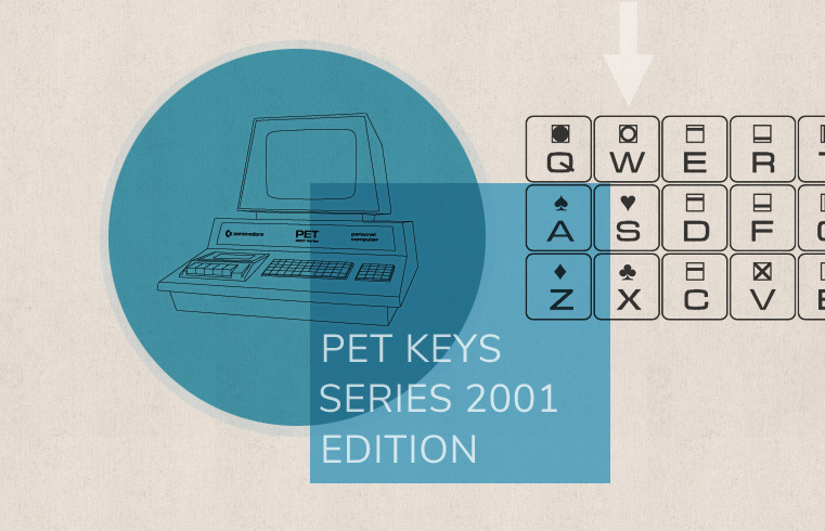
PET Keys — Series 2001 Edition
A closer inspection of the keyboard(s) of the PET 2001.
Back to the PET, 2001 Series, in particular to its keyboard. I just re-implemented the entire keyboard handling for the PET 2001 emulator, which should be to the particular advantage of games and other programs that implement their own keyboard routine in order to detect multiple, concurrent key-presses.
Concurrent key presses on a Commodore 8-bit machine? These machines weren’t especially known for their great N-key rollover, nor for their ability to register multiple keys at once. Probably due to some of the cost-cutting schemes, Commodore was well known for. So, what’s the deal?
The Keyboard Matrix
It’s true, the keyboard scan routines found on the Commodore 8-bits isn’t that great. But this is also not their job, nor their purpose. On the hardware side, things look a bit different, though.
The Keyboard matrix of the PET 2001 consists of 10 rows, which contain the states of each of (up to) 8 keys that are aggregated in a bit-vector. The signal is active LOW, meaning, if there’s no key pressed, the value of the respective bit-vector (or byte) is 0xFF, and, if, say, the key in column 5 is pressed, bit 5 goes low, as in 0xDF (or 255 - 25 = 255 - 32 = 223). This also means that there is a dedicated signal (bit) for each of the 73 keys on the PET’s keyboard and that the keyboard matrix is perfectly able to represent any state of the keyboard, including multiple, concurrent key-presses.
The limitations of the PET’s keyboard are more due to the software side. It is actually a matter of what amount of code and run-time we’re willing to invest. The keyboard scan routine in the Commodore ROM targets “good enough” and “minimal time spent“ (somewhat reasonable, as this runs at every 60Hz interrupt). A game, on the other hand, which is concerned with only a handful of key states, may go more into depth by implementing its own key scan routine. (E.g., you may poll and store the values of the 10 rows and inspect them later for any specific bits.)
But, for a general purpose keyboard routine, there are some trade-offs and decissions to be made. E.g., the BASIC edior can only handle a single key at once, so we have to declare a winner, meaning, this is a lossy operation and we have to throuw some of the information away — and we want this to be performant. The PET 2001 manual states (in bold, pp. 11–13):
Until [the currently pressed] key is released, no other keyboard scans are acknowledged unless a later scanned key is struck. The later scanned key is then considered to be the next key closure. The algorithm does not give classic N key roll over but does allow for legitimate rejection of noise and trapping keys in the order they are struck.
The keyboard is left scanning the last row, which contains the stop key. This allows the routine in BASIC, that checks for the stop key to sample the input I/O device, without having to perform any of the normal functions of scanning. The user can take advantage of this by reading the input character from that row.
This deserves careful reading, as the text is a bit ambiguous: what does “unless a later scanned key is struck” actually mean? In a cursory reading we may understand this is as “if I’m alread holding down a key and then press another one, this latter key replaces the former one as the registered key, which is exactly what I want for N-key rollover.” However, as we will see, this is not what this means.
You may play around with this in the emulator: make sure that the keyboard mode is set to “Games” and click the graphical keyboard with the ALT-key held down, which allows you to simulate multiple key presses at once (clicks toggle keys on and off in this mode). If you have a touch-enabled device, like a tablet, it’s simply multi-touch interaction. Anyways, regardless of how you interact with the keyboard, results may not what you might expect.
Winning the Keyboard Game
So, what key is the winner? Certainly, it is neither the first key pressed, nor is it the last key pressed (as we may have understood the manual). It’s actually based on the key location. Roughly speaking, it is the key the furthest down and, if there should be a tie, it’s the key furthest to the right.
However, in detail it is a bit more complicated than this. To make things a bit more interesting, the logical keyboard columns — as implemented in the keyboard matrix — run through two adjacent columns of the physical layout (so that there are just 8 columns instead of the 16 found on the actual keyboard) and the row property increments towards the right and downwards on this run:
 Physical             Keyboard
 Keyboard              Matrix

                     C0      C1
!  "  #  $ …        0  1    0  1   …
Q  W  E  R …        2  3    2  3   …
A  S  D  E …   =>   4  5    4  5   …
Z  X  C  V …        6  7    6  7   …
SH RV @  [ …        8  9    8  9   …
(In technical terms, columns are compressed by a factor of 2 to fit into byte-size bit-vectors and the thus omitted positions are interleaved in the row dimension of the keyboard matrix.)
In this special game of Snake a key wins, if its row property is higher than any previously scanned key, or, if the row the number is the same and the logical column number is higher. Notably, this is repective to the same scan operation polling consecutively all the rows of the keyboard matrix.
In other words, if we have already found a key, say with the row property of 6 and a (logical) column property of 1 (this would be the letter “C”), a key must have at least a row number greater than or equal 6, and if it is 6, it must have also a higher column number, in order to “win”. Generally, these keys are found further down on the physical keyboard and further to the right on the same row.
However, having a look at the above diagram, this also means that, if the logical row property of our current winner is odd, this is just every second key on the same physical row (as the logical row number alternates, for example, between 3, 2, 3, 2…). On the other hand, if the row number is even, this not only every key to its right, but also the key immediately left to it (e.g., when the row property is 2, so the key left to it has a row property of 3). Any key further down on the physical keyboard has a higher row number anyways and wins per se.
The manual didn’t lie: The winner is actually the last key engaged in the scan order, but it is the last key respective to this very scan procedure, not to key presses latest in time.
And here’s the bigger picture (as we may observe, there are no odd row properties in column 5, which corresponds to the gap in the physical layout, just between the main block and the number pad):
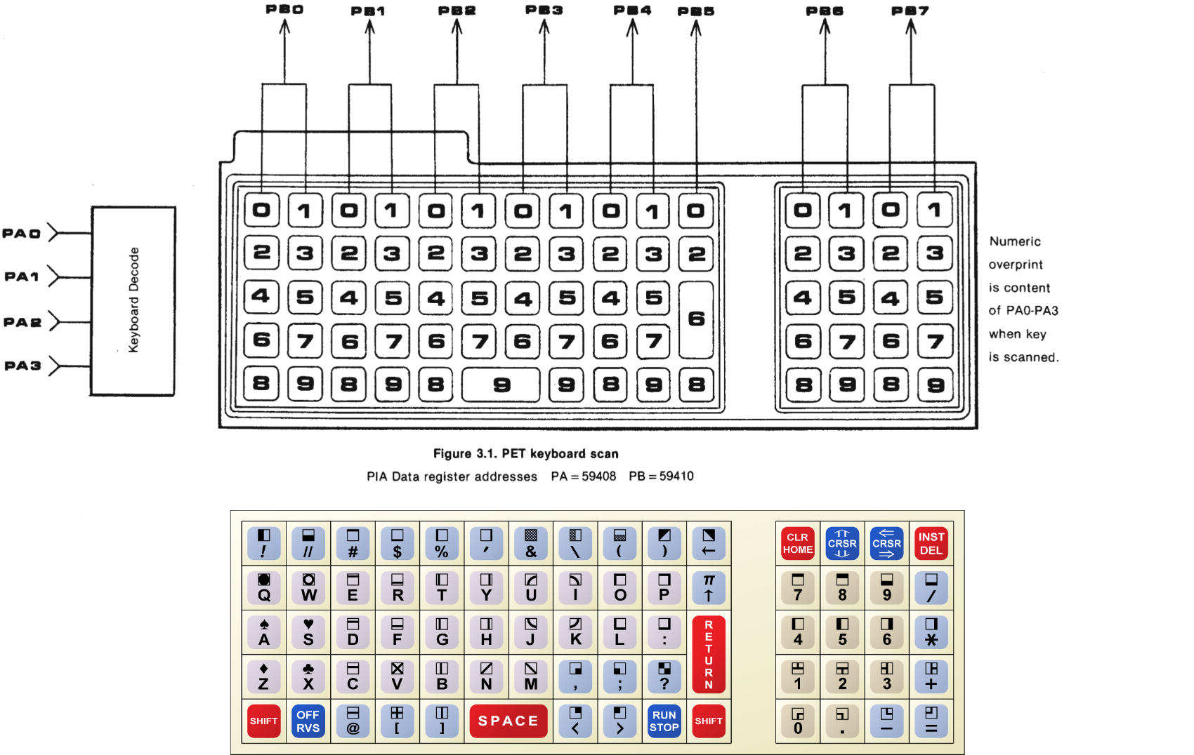
The row currently polled is determined by the value of the low-nibble (bits 0–3) in port A (PA) at $E810 (dec. 59408) of PIA1 (the peripheral interface chip performing the actual scan) and column values are read into port B (PB) at $E812 (dec. 59410).
If we put 2 into the low-nibble of PA, we read all the twos in the above diagram from PB (in logical column order), if we put 8 into PA, we read all the eights, and so on.
This results in the following decoding table ($FF = no key pressed in that row):
| PA $E810 | PB $E812 (column, active low) | |||||||
|---|---|---|---|---|---|---|---|---|
| (row) | 7 | 6 | 5 | 4 | 3 | 2 | 1 | 0 |
| $7F | $BF | $DF | $EF | $F7 | $FB | $FD | $FE | |
| 9 | = | . | n/a | STOP | < | SPACE | [ | RVS |
| 8 | - | 0 | R-SHIFT | > | n/a | ] | @ | L-SHIFT |
| 7 | + | 2 | n/a | ? | , | N | V | X |
| 6 | 3 | 1 | RETURN | ; | M | B | C | Z |
| 5 | * | 5 | n/a | : | K | H | F | S |
| 4 | 6 | 4 | n/a | L | J | G | D | A |
| 3 | / | 8 | n/a | P | I | Y | R | W |
| 2 | 9 | 7 | ↑ | O | U | T | E | Q |
| 1 | DEL | DOWN | n/a | ) | \ | ' | $ | " |
| 0 | RIGHT | HOME | ← | ( | & | % | 3 | ! |
or in terms of key codes:
| PA $E810 | PB $E812 (column, active low) | |||||||
|---|---|---|---|---|---|---|---|---|
| (row) | 7 | 6 | 5 | 4 | 3 | 2 | 1 | 0 |
| $7F | $BF | $DF | $EF | $F7 | $FB | $FD | $FE | |
| 9 | 3D | 2E | FF | 03 | 3C | 20 | 5B | 12 |
| 8 | 2D | 30 | 00 | 3E | FF | 5D | 40 | 00 |
| 7 | 2B | 32 | FF | 3F | 2C | 4E | 56 | 58 |
| 6 | 33 | 31 | 0D | 3B | 4D | 42 | 43 | 5A |
| 5 | 2A | 35 | FF | 3A | 4B | 48 | 46 | 53 |
| 4 | 36 | 34 | FF | 4C | 4A | 47 | 44 | 41 |
| 3 | 2F | 38 | FF | 50 | 49 | 59 | 52 | 57 |
| 2 | 39 | 37 | 5E | 4F | 55 | 54 | 45 | 51 |
| 1 | 14 | 11 | FF | 29 | 5C | 27 | 24 | 22 |
| 0 | 1D | 13 | 5F | 28 | 26 | 25 | 23 | 21 |
0x00 for SHIFT (both left and right SHIFT keys) and 0x03 for STOP. 0xFF marks an empty position in the matrix. Since π is a shifted key (as the sole example for a non-graphical character) and will thus register as 0x5E (“↑”) + SHIFT, there is no conflict with its PETSCII code / BASIC token, which is also 0xFF. (This is the same table, we’ll encounter at ROM address 0xE6F7 [+1] below.)Fun fact: Like various DEC systems, Unix, or CP/M, the PET and other Commodore 8-bits use
^C (0x03, ASCII ETX) to break out of a program. It’s just that they have a dedicated key for this.The Keyboard Scan Routine
In actuality, the keyboard scan routine is a bit different from what we described earlier: it rather brute forces its way by iterating over each of the 80 ($50) row/column combinations (or possible key locations).
For a bit of 6502-fun, here is the core of the routine, as found in the PET 2001 “New ROM”, AKA ROM Set Level 2 (my labels):
;keyboard scan routine (IRQ), PET 2001, ROM 2.0 (New ROM)

E654  A2 50              LDX #$50     ;setup: X <- $50 (key index, 80 keys to scan)

                                      ;setup port A (PA) to read the first row
E656  AD 10 E8           LDA $E810    ;read PIA 1, port A
E659  29 F0              AND #$F0     ;clear low nibble (keyboard row select)
E65B  8D 10 E8           STA $E810    ;and write it back (set up row 0)
(…)
E672  A9 35              LDA #$35     ;setup CRB (Control Register B) for polling
E674  8D 13 E8           STA $E813
(…)
                                      ;main loop

                                      ;read a row and debounce
E68E  A0 08      SCN01   LDY #$08     ;setup: Y <- 8 (number of cols)
E690  AD 12 E8           LDA $E812    ;read PB (cols for current row)
E693  CD 12 E8           CMP $E812    ;recheck content (4 cycles later)
E696  D0 F6              BNE SCN01    ;if changed, redo

                                      ;key decoding (from value read from PB)
E698  4A         SCN02   LSR A        ;shift first/next bit into carry
E699  B0 1C              BCS SCN06    ;bit is high, key not set (active LOW), skip

                                      ;inspect the character
E69B  48                 PHA          ;store remaining PB value on stack
E69C  BD F7 E6           LDA $E6F7,X  ;load char code from table by key index
E69F  D0 06              BNE SCN03    ;not a SHIFT key (code 0)

E6A1  A9 01              LDA #$01     ;load 1
E6A3  85 98              STA $98      ;and set the SHIFT key flag
E6A5  D0 0F              BNE SCN05    ;unconditional jump (no index to store)

E6A7  C9 FF      SCN03   CMP #$FF     ;eval character further, is it $FF?
E6A9  F0 0B              BEQ SCN05    ;empty, n/a: skip
E6AB  C9 3C              CMP #$3C     ;is it the STOP key? (Should be CMP #$03!)
E6AD  D0 05              BNE SCN04    ;no, go store the key index
E6AF  2C 11 E8           BIT $E811    ;check PA control register
E6B2  30 02              BMI SCN05    ;bit 7 set (CA1 transition), do not store…

E6B4  86 A6      SCN04   STX $A6      ;store current key index
E6B6  68         SCN05   PLA          ;restore remaining column bits from stack

                                      ;get ready for the next key position
E6B7  CA         SCN06   DEX          ;decrement key index
E6B8  F0 08              BEQ SCN07    ;zero: all 80 keys done, exit loop
E6BA  88                 DEY          ;decrement Y (from initial 8)
E6BB  D0 DB              BNE SCN02    ;bits left, redo for next col in same row
E6BD  EE 10 E8           INC $E810    ;poll next row (increment row number in PA)
E6C0  D0 CC              BNE SCN01    ;unconditional jump, read that row

                                      ;end of main loop

                                      ;evaluate final result
E6C2  A5 A6      SCN07   LDA $A6      ;load the key index, we’ve found
(…)
As we may observe, the X register holds the number of keys to inspect, which also serves as a general key index and an index into a lookup table, much like we’ve seen it above. After a preliminary setup of the ports, we’re ready to commence the actual scanning.
The first step is a read and debounce logic: we read the current value for a row (the aggregated column signals) from port B ($E812) and immediately compare this to what’s in port B. This “immediately” is 4 microseconds later, as 4 processor cycles at 1MHz have passed. If this is the same, we have a stable signal. Otherwise, we redo and the initilization of register Y to the umber of bits to process for a row provides a convenient delay for a fresh capture.
Then we inspect the least significant bit by shifting it into the carry bit. if it’s high, there is no signal (it’s active LOW) and we skip to the preparations for reading the next bit. Otherwise, we store the remaining bits in the accumulator, which are awaiting further inspection, on the stack and load a character value from the lookup table. As the character in X consecutively decrements in each iteration of this loop, we get a new value for each key location. If it is a valid key, we store it in $A6 and pull the remaining bits from the stack.
In-between are a few further checks for the SHIFT key and for the STOP key. The reason for this is that those are not stored as a key code, rather, the SHIFT keys have their own flag in $98, and for the STOP key, it depends on the state of the control register for VIA port A, bit 7.
Apparently this is related to cassette operations and it is here that we encounter an actual bug: Reportedly, this specific implementation (in the BASIC 1 and BASIC 2 ROMs) has issues with the “<” key pressed during cassette operations. Indeed, $3C is the PETSCII code for “<”. (Which is probably, why this particular part of the code looks different on the C64, which also switches the roles of the X and Y registers.) We’ll have a closer look at this below.
Anyways, that these checks have to be made for each of the 80 positions of the key matrix is a result of the brute force scheme, since, at the end, this could be overwritten by any of the following key checks. And we really do not want to miss these keys! At first glance, this may seem rather wasteful, but, over all, a key pressed is a rare occasion in the life of a computer and this code will be rarely executed, all.
Finally, we reiterate. If there are bits left to inspect in a row, we redo at label SCN02, otherwise, we read the next row at SCN01. If, however, we done with all of the 80 key positions, we jump to label SCN07, where we continue by reading the final key index from $A6.
As we may see, if there have been multiple key presses, any active key processed will overwrite the key index in $A6. The remaining “winner“ is the last active key in scan order, which iterates consecutively over the rows of the matrix, from the 0 to 9, and (logical) column positions checked from left to right.
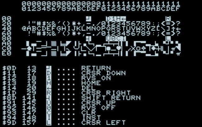
The winning key index is then transformed via the lookup table, which results in a PETSCII code like these (mind that there is no code for SHIFT or STOP), where shifted characters have their sign-bit set (resulting in codes ≥ $80):
| 00 | 01 | 02 | 03 | 04 | 05 | 06 | 07 | 08 | 09 | 0A | 0B | 0C | 0D | 0E | 0F | 10 | 11 | 12 | 13 | 14 | 15 | 16 | 17 | 18 | 19 | 1A | 1B | 1C | 1D | 1E | 1F | |
| 0x00 | C R | D W N | R V S | H O M | D E L | R G T | ||||||||||||||||||||||||||
| 0x20 | ! | " | # | $ | % | & | ' | ( | ) | * | + | , | - | . | / | 0 | 1 | 2 | 3 | 4 | 5 | 6 | 7 | 8 | 9 | : | ; | < | = | > | ? | |
| 0x40 | @ | A | B | C | D | E | F | G | H | I | J | K | L | M | N | O | P | Q | R | S | T | U | V | W | X | Y | Z | [ | \ | ] | ↑ | ← |
| 0x60 | ! | " | # | $ | % | & | ' | ( | ) | * | + | , | - | . | / | 0 | 1 | 2 | 3 | 4 | 5 | 6 | 7 | 8 | 9 | : | ; | < | = | > | ? | |
| 0x80 | S C R | U P | R O F | C L R | I N S | L F T | ||||||||||||||||||||||||||
| 0xA0 | ▌ | ▄ | ▔ | ▁ | ▏ | ▒ | ▕ | ▄ | ◤ | ▄ | ├ | ▗ | └ | ┐ | ▂ | ┌ | ┴ | ┬ | ┤ | ▎ | ▍ | ▐ | ▔ | ▀ | ▃ | ▟ | ▖ | ▝ | ┘ | ▘ | ▚ | |
| 0xC0 | ─ | ♠ | │ | ─ | ─ | ▔ | ─ | │ | │ | ╮ | ╰ | ╯ | ▙ | ╲ | ╱ | ▛ | ▜ | ● | ▁ | ♥ | ▏ | ╭ | ╳ | ○ | ♣ | ▕ | ♦ | ┼ | ▌ | │ | π | ◥ |
| 0xE0 | ▌ | ▄ | ▔ | ▁ | ▏ | ▒ | ▕ | ▄ | ◤ | ▄ | ├ | ▗ | └ | ┐ | ▂ | ┌ | ┴ | ┬ | ┤ | ▎ | ▍ | ▐ | ▔ | ▀ | ▃ | ▟ | ▖ | ▝ | ┘ | ▘ | π |
Note: 0x60–0x7F is a copy of 0x20–0x3F. PETSCII graphics characters are here provided as approximations found in basic Unicode ranges. (Sadly, there are few fonts that would support the “Symbols for Legacy Computing” range.)
Or, if you prefer a more authentic presentation:
For more on the PETSCII character set and how its organization relates to the chiclet keyboard of the PET 2001, see the earlier post ”PETSCII Revealed”.
The Bug
It’s time, we have a closer look at the bug: The STOP key is on row 9, the last row polled, with a column index of 4. Meaning, there are only 3 more keys to check, and, as we’re counting down to 1 (and exit the loop as soon as we decrement the index to zero), this means that the STOP key has a key index of 4. This key index is held in the X register and is added to the base address of the lookup table at $E6F7, when we fetch the character code.
And this is what the lookup table looks like (0xFF = no such key):
E6F7: 60
E6F8: 3D 2E FF 03 3C 20 5B 12   =.··< [·
E700: 2D 30 00 3E FF 5D 40 00   -0·>·]@·
E708: 2B 32 FF 3F 2C 4E 56 58   +2·?,NVX
E710: 33 31 0D 3B 4D 42 43 5A   31·;MBCZ
E718: 2A 35 FF 3A 4B 48 46 53   *5·:KHFS
E720: 36 34 FF 4C 4A 47 44 41   64·LJGDA
E728: 2F 38 FF 50 49 59 52 57   /8·PIYRW
E730: 39 37 5E 4F 55 54 45 51   97↑OUTEQ
E738: 14 11 FF 29 5C 27 24 22   ···)\'$"
E740: 1D 13 5F 28 26 25 23 21   ··←(&%#!
We may observe that the value at (the zero-based) index 4 in the table is 0x03 — and that 0x3C, the code for “<”, is immediately next to it with an index of 5. So the check should really be “CMP #$03”!
There are actually multiple ways that this could happen: First, it could be a a simple counting error, a classic one-off fault. Especially, as we are counting down from 0x50 (decimal 80) and are leaving the procedures as soon as we decrement to zero. (Meaning, while it’s a zero-based index, the index zero is never used.) So it may be a logical error, as well. Or, it could be due to an erroneous interpretation of the scan procedures, where we tackle the individual bit checks from the wrong side in our mental model, as shifting to the left instead of the ASR right-shift, in which case we would also arrive at 0x3C. (A classic case of dyslexia?)
Having that said, it’s not exceedingly likely that this originated from the side of interpreting the key index, as this could then have been a simple check for the X register (as in CPX). Instead, the code tackles this entire problem from the side of the character codes in the lookup table. I guess, someone just picked the wrong, adjacent value from the table. Whatever the reason, this piece of codes never checks for the STOP key, but for the “<” key, instead!
But we are also lucky, as this only handles a special case where the STOP key should not be registered. Therefore, apart from rare issues related to cassette operations, where the “<” key wouldn’t be recognized when bit 7 of the conytrol register CA1 is high, we won’t notice, at all.
Keyboards
What we described here is the original chiclet keyboard of the PET 2001, but there are others, as well, three types in all: the well known chiclet keyboard, the graphics keyboard of the PET 2001N, and finally, the business keyboard of the PET 2001/B. The latter two are also found on later PETs.
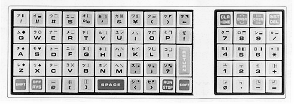
Not much is known of the respective input mode. Image: source (enhanced).
For more on this Japanese edition of the PET 2001 keyboard see also this post,
“Japanese Attractions: Kana on the PET 2001”.
This is what BYTE Magazine had to say about the chiclet keyboard:
A much criticized feature of the PET is the design of the keyboard itself. It is a calculator style keyboard rather than a true typewriter keyboard. The keys are small and flat (about a half inch square and a quarter inch deep). They are tightly packed next to each other and are arranged in vertical rows rather than the slanting rows used on a typewriter keyboard. Although the alphabet follows the usual typewriter layout, the PET keyboard really cannot be used for touch typing because of the size, depth and spacing of the keys. The keyboard is said to be reliable and long lasting, but did find that the space bar would not register correctly unless it was pressed squarely in the middle. Certainly the keyboard lowers the cost of the unit somewhat, and Commodore points out that their keyboard provides a larger number of keys and hence more graphic characters, but it is definitely more difficult to use. As a result many personal computer users may try to interface a separate typewriter style ASCII keyboard to the PET.
Dan Fylstra, “User's Report: The PET 2001.” in: BYTE, Vol. 3 No. 3, March 1978, p.120
And this is what such an aftermarket keyboard looked like:
(Any such keyboard would have to replicate the keyboard matrix in order to interface with the PET.)
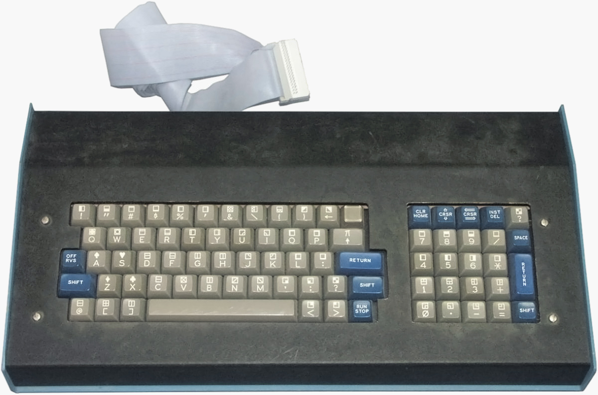
Image: Daves Old Computers (edited).
Update: And here is another image, showing the Maxi Switch keyboard in alternative packaging for mounting on the PET (with the cassette drive removed), and the KB-74 by Skyles Electricworks. Mind how the original chiclet keyboard compares in size to these full-size keyboards.
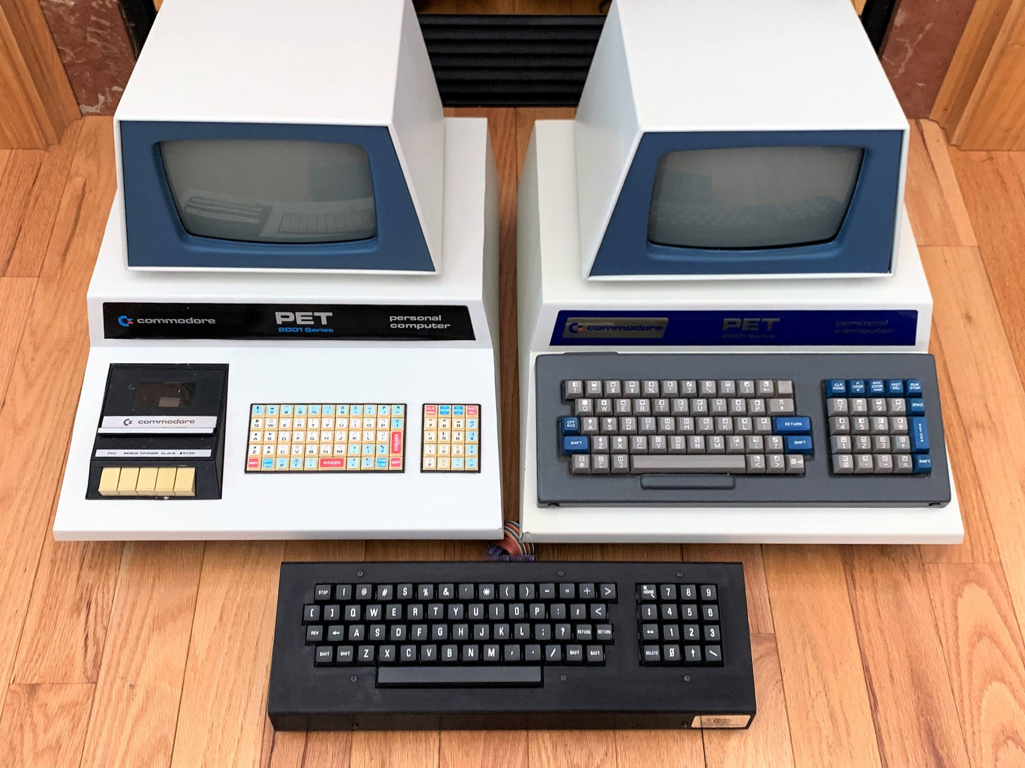
Note the diminutive size of the original chiclet keyboard in comparison to these regular size ones.
Image: Santo Nucifora / @vintagecomputer.ca (Bluesky), 2025.
PET 2001N
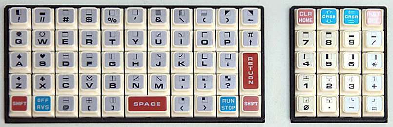
The PET 2001N, otherwise unaltered from the original release (*), came with the graphics keyboard. This featured actual keys with the PETSCII block graphics characters printed on the front of the key caps. And, while it changed a few key positions on the physical layout, the keyboard matrix remained the same, no changes required in ROM or on the software side of things.
*) Note: While the PET 2001N was esentially still the original machine, the larger graphics keyboard came at the expense of the built-in cassette deck and the PET 2001N also added additional ROM slots, which could accommodate the more extensive 4.0 ROM set and option ROMs in the $9000–$BFFF range. — Thus, the entire 64K address range of the 6502 was now mapped to either RAM (up to 32K), video RAM (4 × 1K, mirrored), I/O (2K), or ROM.
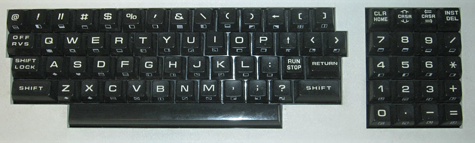
As may be expected, this causes a few disturbances in the physical arrangement of the keyboard matrix:
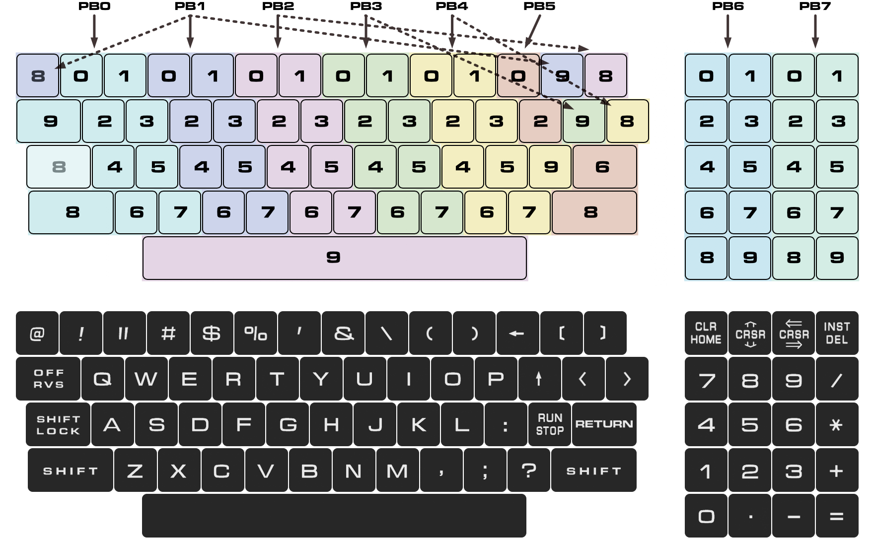
Numbers in the upper part give the row index as in PA0–PA3.
As a consequence, the rollover behavior isn’t always that predictable and straight-forward as it had been with the original keyboard. (E.g., the square brackets and the at-sign will take precedence over any other key in the topmost physical key row, as do the reverse key and the less-than and greater-than keys in the second one.) The price of progress…
PET 2001/B
The PET 2001 wasn’t only one of the first ready-to-run monolythic home computers, it was also a serious business machine. For this it got a special business keyboard, thus becoming the “Series 2001/B Business Computer”, or, with respect to its label, a “professional computer”.
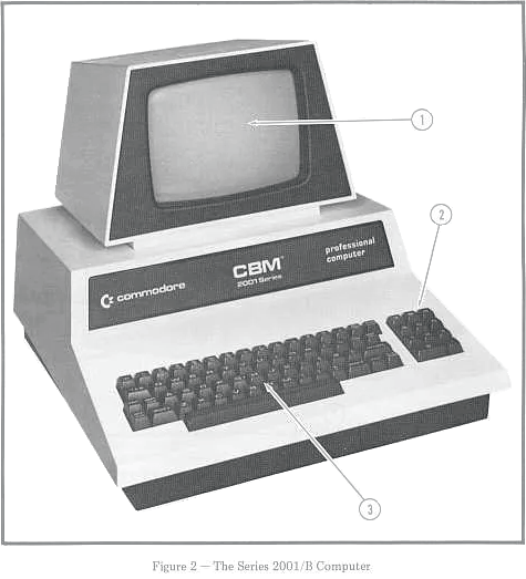
Image: Commodore Business Computer User’s Guide
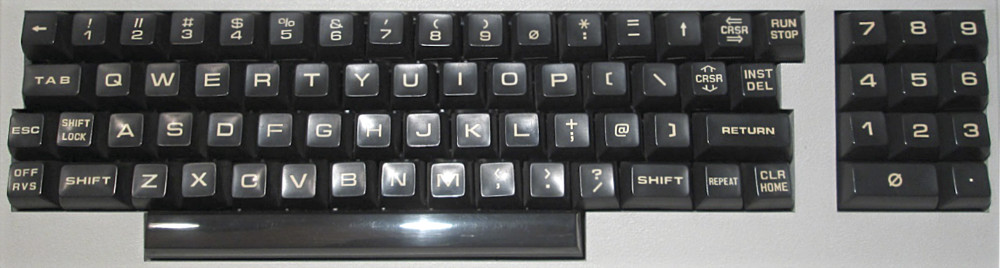
The business keyboard is another beast, though. Like the chiclet keyboard and the graphical keyboard it features 73 keys, but these are different keys in a different arrangement and these come with their own logic. The most notable difference is that, while the chiclet keyboard and the graphical keyboard have all the conventional ASCII characters readily available on the first level (with SHIFT being reserved for the graphics characters and opposite functions for non-printing keys), the business keyboard makes ample use of shifted keys for punctuations and special characters. Moreover, numbers are now available typewriter-style on the topmost key row and on a separate numeric keypad, each coming with their dedicated positions in the keyboard matrix. (So these are not the same keys by any means and a program can detect the difference.) This has also made room for four additional keys, three of them state modifiers, namely TAB, ESC, REPEAT, and CAPS-LOCK. On the downside, this means that the beloved PETSCII graphics characters enjoy a decided backseat. There is no notion of them, at all, and there are no hints on how to input them. Apparently, a serious, “professional computer” doesn’t deserve them.
The keyboard matrix is a bit weird: At the left side, where we find PB0 and PB1, everything is still fine and orderly, but as we move to the right side, the arrangement becomes more and more askew and and convoluted, and the areas covered by the individual columns are even discontinuous. And, on top of this, PB4 isn’t in the middle, as we might expect it, but moved to the right, just before PB7, covering keys both at the right edge of the main key block and on the numeric keypad. (Hence, STOP is still column 4, row 9.)
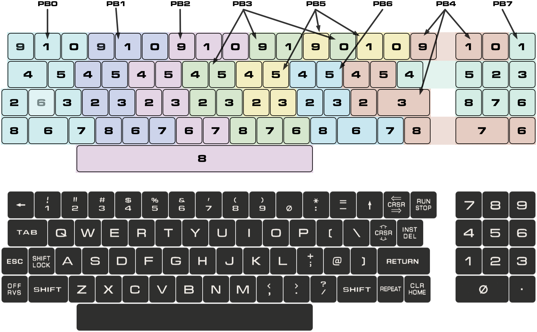
The interleaf of columns PB3 and PB5 in the physical top row may be indicative of a change rather late in the design process, where the “
:” and “−” keys switched their respective locations.(Reports of me preparing an implementation of the business keyboard may be exaggerated.)
And this is how this works out as a table:
| PA $E810 | PB $E812 (column, active low) | |||||||
|---|---|---|---|---|---|---|---|---|
| (row) | 7 | 6 | 5 | 4 | 3 | 2 | 1 | 0 |
| $7F | $BF | $DF | $EF | $F7 | $FB | $FD | $FE | |
| 9 | ^V | n/a | : | STOP | 9 | 6 | 3 | ← |
| 8 | k1 | / | ^U | HOME | m | SPACE | x | RVS |
| 7 | k2 | RPT | ^O | k0 | , | n | v | z |
| 6 | k3 | R-SHIFT | ^Y | k. | . | b | c | L-SHIFT |
| 5 | k4 | [ | o | DOWN | u | t | e | q |
| 4 | DEL | p | i | \ | y | r | w | TAB |
| 3 | k6 | @ | l | RETURN | j | g | d | a |
| 2 | k5 | ; | k | ] | h | f | s | ESC |
| 1 | k9 | n/a | ↑ | k7 | 0 | 7 | 4 | 1 |
| 0 | n/a | L+R-SHFT | RIGHT | k8 | - | 8 | 5 | 2 |
kN … key N located on the numeric keypad^Char … control character (neither obvious nor intuitive to enter)The unshifted default case is now lower-case, as opposed to the original PET 2001 character generator, where unshifted characters were always upper-case and shifted characters were either lower-case or graphics characters, depending on the screen mode. (Logically this is still the same, it’s just that the glyphs were switched around in the character ROM.)
and per key code:
| PA $E810 | PB $E812 (column, active low) | |||||||
|---|---|---|---|---|---|---|---|---|
| (row) | 7 | 6 | 5 | 4 | 3 | 2 | 1 | 0 |
| $7F | $BF | $DF | $EF | $F7 | $FB | $FD | $FE | |
| 9 | 16 | 04 | 3A | 03 | 39 | 36 | 33 | DF |
| 8 | B1 | 2F | 15 | 13 | 4D | 20 | 58 | 12 |
| 7 | B2 | 10 | 0F | B0 | 2C | 4E | 56 | 5A |
| 6 | B3 | 00 | 19 | AE | 2E | 42 | 43 | 00 |
| 5 | B4 | DB | 4F | 11 | 55 | 54 | 45 | 51 |
| 4 | 14 | 50 | 49 | DC | 59 | 52 | 57 | 09 |
| 3 | B6 | C0 | 4C | 0D | 4A | 47 | 44 | 41 |
| 2 | B5 | 3B | 4B | DD | 48 | 46 | 53 | 9B |
| 1 | B9 | 06 | DE | B7 | B0 | 37 | 34 | 31 |
| 0 | 05 | 0E | 1D | B8 | 2D | 38 | 35 | 32 |
Greyed out codes are marked invalid (0xFF) in the ROM table, see below.
and this is the related lookup table (BASIC 4, 0xFF = no such key):
E60A: 60
E60B: FF FF 3A 03 39 36 33 DF   ··:·963←
E613: B1 2F FF 13 4D 20 58 12   1/··M X·
E61B: B2 10 FF B0 2C 4E 56 5A   2··0,NVZ
E623: B3 00 FF AE 2E 42 43 00   3··..BC·
E62B: B4 DB 4F 11 55 54 45 51   4[O·UTEQ
E633: 14 50 49 DC 59 52 57 09   ·PI\YRW·
E63B: B6 C0 4C 0D 4A 47 44 41   6@L·JGDA
E643: B5 3B 4B DD 48 46 53 9B   5;K]HFS·
E64B: B9 FF DE B7 B0 37 34 31   9·↑7·741
E653: FF FF 1D B8 2D 38 35 32   ···8-852
(Underlined, grey-blue characters are located on the numeric keypad. Mind how some punctuations or special characters do not appear by their usual PETSCII codes, but rather have a code of > 0x80.)
Mind that any keys located at the numeric keypad of the business keyboard, while having distinctive their own, distinctive character codes in the keyboard matrix (e.g., keypad 1…9 are 0xB0…0xB9, and 1…9 on the main key block are 0x31…0x37, while 0 is 0xB0 for both), will produce the usual PETSCII characters, when scanned by the ROM keyboard scan routine. Moreover, there is no way to enter any of the block character graphics in the range fo PETSCII codes 161 to 191 (0xA1…0xBF) by a simple key-press.
The business keyboard isn’t only lacking any block character graphics legends on its key caps, it simply doesn’t support these characters, except those doubling as upper-case characters in the Upper-Case/Lower-Case character set.
Key Legends — What’s the Font?
I see mentioned that the PET keyboard used ‘Microgramma D Bold Extended’ for the key caps legends. However, this isn’t really the case. At least for the big letter legends the font is too bold and often too extended (wide). If this was ever a proper font, it has not been brought over to the modern digital era.
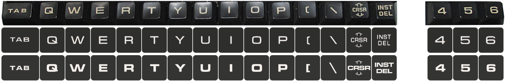
Top: the “real thing”, middle: my attempt, bottom: Microgramma D Bold Extended.
Note: The chiclet keyboard used a heavier variant for its legends, and I’m aware that there are at least graphics keyboards with a heavier font. (But I haven’t seen those with the PET 2001 specifically.)
What I ended up using for the graphics of the business keyboard was:
- For the big letter legends I found that it was easier to start with a font too thin than with a font that is too bold. Hence, I imported ‘Microgramma D Medium Extended’ into FontForge and emboldened the glyphs somewhat in a global operation and then adjusted various glyphs in their width. This was still a bit too thin, but you can go only that far before distorting the outlines…
- The small, bold legends, like those found in the first key row are ‘Euro Technic Extended Bold’, a font very similar to ‘Microgramma D Bold Extended’. This was slightly too bold. A few glyphs are in actual ‘Microgramma D Bold Extended’, though.
- For the small legends of non-printing function keys like “CRSR” or “RUN STOP” I used ‘Microgram DB Regular’, a font similar to a non-extended Microgramma. This is often squished, meaning rendered in reduced width, as found on the real key caps. As this font is pretty linear, it’s pretty robust to this operation. Again, this font was too thin to meet the real object.
Finally, the glyphs were adjusted for visual weight in Photoshop, mostly using masks and mask refinements. Some glyphs, like the figure zero (“0”), the brackets (“(”, “)”), the less-than and greater-than signs (“<”, “>”), and the left and up arrows (“←”, “↑”) aren’t any font glyphs at all, and I don’t think that they are in the original, but rather graphics. Others, like the exclamation mark, the double and single quotes, the asterisk, the dash and the slashes, the square brackets, and the at sign (“@”) are heavily modified. (The percent sign, “%”, isn’t right either, as the slash should be nearly upright, but every reconstruction should show a significant deviation from the real thing in order to show that it isn’t really what it suggests to be.)
This should suffice to show that ‘Microgramma D Bold Extended’ takes you only that far in the right direction. In order to do this properly, you really ought to draw a fresh font, and you may have to so in 3 weights, a semibold one (probably a bit on the heavy side) for the big key legends, a more extended bold one for the small key legends, and finally a slightly conedensed medium one for the legends of the non-printing function keys. (Suggested: “PETgramma Semibold”, “PETgramma Bold Extended“ and “PETgramma Medium Condensed”.)
Well, these concerns regarding the right font appearance may seem nitpicky, even petty — but, as it is about the PET, I‘m fine with that. ;-)
Appendix: How To
However, we still don’t know how to read multiple keys, on the PET, at once.
Having a look at the ROM routine, we may see that all it takes to read the first row is:
                                      ;setup port A (PA) to read the first row
E656  AD 10 E8           LDA $E810    ;read PIA 1, port A
E659  29 F0              AND #$F0     ;clear low nibble (keyboard row select)
E65B  8D 10 E8           STA $E810    ;and write it back (set up row 0)
                                      ;read a row and debounce
E68E  A0 08      SCN01   LDY #$08     ;setup: Y <- 8 (number of cols)
E690  AD 12 E8           LDA $E812    ;read PB (cols for current row)
E696  D0 F6              BNE SCN01    ;if changed, redo
Which leaves us with the column vector of row 0 in the accumulator (A).
However, when we’re reading multiple keys at once, like for a game, we’re probably not interested in debouncing, we just want to capture the current state. Considering this, we may condense this into a short routine that allows us to query the state of a specific key:
PA = $E810
PB = $E812
                            ;test row in A against bit-vector in X
KEYTEST     ORA #$F0
            STA PA          ;select row
            TXA             ;transfer bit vector from X into A
            AND PB          ;mask it by columns read from PB
            RTS             ;zero-flag set for match
Mind the instruction “ORA #$F0” at label “KEYTEST”. Here, we have to consider that Port A of PIA 1 not only selects the row of the keyboard matrix, but also shares this with a few signals in the high-nibble, which are controlling the cassette motor(s) and the IEEE EOI-in signal:
PIA 1, Port A
$E810	bit       meaning

         6        IEEE EOI in
         5        cassette sense #2
         4        cassette sense #1
        3–0       keyboard row select
All these signals are active low, meaning, if we were to put naïvely, say, $03 into this register, in order to select row #3, we are to interfere with the signals in the high-nibble and may activate things. E.g., if there are any cassette drives (Datasettes) attached, this may start the cassette motor. In a ”controlled environment”, we may ignore the current state and assume that none of these signals are low, as none of the drives involved are in active use. But we’ll have still to make sure that these bits are set to high (the neutral default state), as in $F3.
So, instead of writing:
            LDA $E810
            AND #$F0
            CLC
            ADC #3
            STA $E810
we’ll just use:
            LDA #$F3
            STA $E810
Also mind that we really sould have interrupts disable when calling this. Just to be sure, we’re actually reading from the row, we have setup in PA — as we should always do, when interfacing with the hardware like this. (Speaking of hardware, this and the following examples are for a PET with the graphics keyboard, chiclet or “real” keys.)
And here is a more complete example:
;read WASD and display it at the top of the screen

PA = $E810
PB = $E812
VIDEO = $8000


            .PETSTART       ;compiles BASIC header and sets origin

            SEI             ;disable interrupts

LOOP
                            ;check "W": row 3 col 0
            LDY #0x20       ;load a blank as the default output
            LDA #$F3        ;row 3
            LDX #%00000001  ;col 0
            JSR KEYTEST     ;test it
            BNE OUTW        ;zero-flag indicates a match
            LDY #$97        ;screen code for reverse "W": $17 + $80
OUTW        STY VIDEO       ;output at top of the screen

                            ;check "A": row 4 col 0
            LDY #0x20
            LDA #$F4
            LDX #%00000001
            JSR KEYTEST
            BNE OUTA
            LDY #$81
OUTA        STY VIDEO+1
                            ;check "S": row 5 col 0
            LDY #0x20
            LDA #$F5
            LDX #%00000001
            JSR KEYTEST
            BNE OUTS
            LDY #$93
OUTS        STY VIDEO+2
                            ;check "D": row 4 col 1
            LDY #0x20
            LDA #$F4
            LDX #%00000010
            JSR KEYTEST
            BNE OUTD
            LDY #$84
OUTD        STY VIDEO+3
                            ;check STOP key: row 9 col 4
            LDA #$F9
            LDX #%00010000
            JSR KEYTEST
            BNE LOOP        ;redo unless STOP
            CLI             ;enable interrupts
            RTS             ;and quit


KEYTEST     STA PA          ;checks row in A against bit-vector in X
            TXA
            AND PB
            RTS             ;zero-flag set for match

            .END
You may try it out in the PET 2001 emulator (with a bit of chrome added, see the source here.)
(The principal machanism will be the same for other Commodore 8-bits, but you will have to adjust the hardware addresses and any of the values used for the keyboard matrix.)
If we’d want to inline just a single check, we may do something like this:
;check, if key "A" is pressed (row 4 col 0)

PA = $E810
PB = $E812

            LDA #$F4
            STA PA          ;select row 4
            LDA PB
            AND #%00000001  ;col 0 → mask bit 0
            BEQ ON_KEY_A    ;active low signal → branch to key handler
Compared to the subroutine approach, this saves 18 CPU cycles at the cost of one additional byte.
(7 versus 8 bytes per test, AND immediate = 2 cycles, while JSR is 6 cycles and the subroutine 14 cycles.)
The subroutine approach may pay off, if we use this to collect the state of a few keys in a bit-vector, instead of checking each key on it’s own. E.g., we may accumulate flags for directional movements in order to handle this similar to joystick readings:
;collect flags for WSAD and SPACE in byte KBD (↑,↓,←,→,button)

PA = $E810
PB = $E812

            LDA #0          ;initialize KBD vector
            STA KBD
                            ;read "W": row 3 col 0
            LDA #$F3
            LDX #%00000001
            JSR READKEY
                            ;read "S": row 5 col 0
            LDA #$F5        ;X is still %00000001
            JSR READKEY
                            ;read "A": row 4 col 0
            LDA #$F4        ;X is still %00000001
            JSR READKEY
                            ;check "D": row 4 col 1
            LDA #$F4
            LDX #%00000010
            JSR READKEY
                            ;read SPACE: row 9 col 2
            LDA #$F9
            LDX #%00000100
            JSR READKEY

                            ;KBD holds 0-0-0-W-S-A-D-SPACE (active high)
            ...             ;now do something


READKEY     CLC             ;clear carry
            STA PA          ;row in A
            TXA             ;col in X
            AND PB
            BNE READKEYSL
            SEC             ;set carry, if key is pressed
READKEYSL   ROL KBD         ;shift left with carry now in bit 0
            RTS


KBD
            .BYTE 0
Try it in the PET 2001 emulator (see the source here.)
(Note: to make this active low, like a joystick attached to VIA port A via the user port, swap the CLC and SEC instructions in routine READKEY and initialize KBD to $FF, rather than to 0.
Mind that some joystick adapter schemes combine signals for “up” and ”down” to encode the “fire” button, which is perfectly possible to enter accidentally using the keyboard. So be careful when reusing code…)
Another, probably better behaved approach is to fetch the entire key matrix at once and to store it in a small table (of 10 bytes), which also allows us to disable interrupts and to properly mask and preserve the higher bits in PA that are crucial for I/O operations:
PA = $E810
PB = $E812
CRB = $E813
                            ;fetch all key rows and store them at KEYROWS
FETCHKEYS   SEI             ;disable interrupts
            LDA PA          ;set up PA for row 0
            AND #$F0        ;clear bits 0-3
            STA PA
            LDA #$35        ;set up CRB (Control Register B)
            STA CRB         ;(somewhat optional)
            LDX #0          ;initialize counter in X
READROW     LDA PB          ;read row
            STA KEYROWS,X   ;store it
            INX             ;increment counter
            CPX #10         ;10 rows done?
            BEQ ROWSDONE    ;yes, break out of loop
            INC PA          ;set up next row
            BNE READROW     ;and loop (unconditionally)
ROWSDONE    CLI             ;enable interrupts again
            RTS


KEYROWS                     ;store of 10 bytes for 10 key rows (active low)
            .BYTE $FF
            .BYTE $FF
            .BYTE $FF
            .BYTE $FF
            .BYTE $FF
            .BYTE $FF
            .BYTE $FF
            .BYTE $FF
            .BYTE $FF
            .BYTE $FF
            .BYTE $FF
(Setting up CRB, as well as data direction registers, is somewhat optional, assuming that the PET is in a state where it is ready to accept keyboard input.)
After calling the routine FETCHKEYS, the entire key matrix is captured and stored in the table KEYROWS in the correct row order (0…9). Now we may come back to this anytime and inspect the state of individual keys. Again, here is a more complete example:
;read WASD and display it at the top of the screen

PA = $E810
PB = $E812
CRB = $E813
VIDEO = $8000


            .PETSTART       ;compiles BASIC header and sets origin

LOOP        JSR FETCHKEYS

                            ;check "W": row 3 col 0
            LDY #0x20       ;load a blank as default output
            LDA KEYROWS+3   ;get the row
            AND #%00000001  ;check col
            BNE OUTW        ;set? (active low)
            LDY #$97        ;screen code reverse "W": $17 + $80
OUTW        STY VIDEO       ;output at top of screen

                            ;check "A": row 4 col 0
            LDY #0x20
            LDA KEYROWS+4
            AND #%00000001
            BNE OUTA
            LDY #$81
OUTA        STY VIDEO+1
                            ;check "S": row 5 col 0
            LDY #0x20
            LDA KEYROWS+5
            AND #%00000001
            BNE OUTS
            LDY #$93
OUTS        STY VIDEO+2
                            ;check "D": row 4 col 1
            LDY #0x20
            LDA KEYROWS+4
            AND #%00000010
            BNE OUTD
            LDY #$84
OUTD        STY VIDEO+3
                            ;check STOP key: row 9 col 4
            LDA KEYROWS+9
            AND #%00010000
            BNE LOOP        ;redo unless STOP
            RTS


FETCHKEYS   SEI             ;fetch all key rows and store them at KEYROWS
            LDA PA          ;set up PA for row 0
            AND #$F0
            STA PA
            LDA #$35        ;set up CRB
            STA CRB
            LDX #0
READROW     LDA PB          ;read row
            STA KEYROWS,X   ;store it
            INX
            CPX #10         ;10 rows done?
            BEQ ROWSDONE
            INC PA          ;set up next row
            BNE READROW     ;and loop (unconditionally)
ROWSDONE    CLI
            RTS


KEYROWS                     ;store of 10 bytes for 10 key rows (active low)
            .BYTE $FF
            .BYTE $FF
            .BYTE $FF
            .BYTE $FF
            .BYTE $FF
            .BYTE $FF
            .BYTE $FF
            .BYTE $FF
            .BYTE $FF
            .BYTE $FF
            .BYTE $FF

            .END
Again, you may try it out in the PET 2001 emulator (with a bit of chrome added, see the source here.)
Norbert Landsteiner,
Vienna, 2023-08-03